4D Bioprinting for Dynamic Tissue Structures: A New Era in Regenerative Medicine and Drug Development
This article provides a comprehensive analysis of 4D bioprinting, an advanced additive manufacturing technology that creates dynamic, stimuli-responsive tissue constructs.
4D Bioprinting for Dynamic Tissue Structures: A New Era in Regenerative Medicine and Drug Development
Abstract
This article provides a comprehensive analysis of 4D bioprinting, an advanced additive manufacturing technology that creates dynamic, stimuli-responsive tissue constructs. Tailored for researchers, scientists, and drug development professionals, it explores the foundational principles of smart biomaterials and their transformation mechanisms. The scope extends to detailed methodologies, key biomedical applications in tissue engineering and disease modeling, and critical troubleshooting of current technical and material limitations. Furthermore, it examines validation frameworks through mathematical modeling, comparative performance analysis, and in vivo testing, offering a holistic perspective on this transformative technology's potential to revolutionize regenerative medicine, pharmaceutical testing, and personalized healthcare.
The Foundations of 4D Bioprinting: From Smart Materials to Shape Transformation
Four-dimensional (4D) bioprinting represents a paradigm shift in biofabrication, building upon the foundation of three-dimensional (3D) bioprinting by introducing time as a functional dimension. This advanced technology enables the creation of dynamic, adaptive constructs that can undergo predetermined morphological or functional changes in response to specific stimuli over time [1] [2]. While 3D bioprinting produces static structures with fixed geometry, 4D bioprinting harnesses stimuli-responsive biomaterials and/or inherent cell forces to generate structures that evolve post-printing, more accurately recapitulating the dynamic nature of native tissues [3] [4].
The fundamental distinction lies in material responsiveness. Traditional 3D bioprinting focuses on structural fidelity and biocompatibility with static outputs, whereas 4D bioprinting prioritizes temporal programming and adaptive behavior, allowing constructs to transform their shape, properties, or functionality in response to environmental cues such as temperature, pH, light, or magnetic fields [5] [2]. This capability is particularly valuable for regenerative medicine, where tissues naturally undergo continuous remodeling during development, healing, and normal physiological function [3].
Mechanisms of 4D Transformation
The dynamic behavior of 4D-bioprinted structures arises from two primary mechanisms: the use of smart materials that respond to external stimuli, and the harnessing of intrinsic biological forces generated by living cells.
Stimuli-Responsive Biomaterials
Stimuli-responsive biomaterials, often termed "smart materials," form the cornerstone of many 4D bioprinting systems. These materials undergo controlled physicochemical transformations when exposed to specific environmental triggers [1] [5]. The table below summarizes the major categories of stimuli-responsive materials used in 4D bioprinting.
Table 1: Categories of Stimuli-Responsive Biomaterials for 4D Bioprinting
| Stimulus Type | Material Examples | Response Mechanism | Potential Applications |
|---|---|---|---|
| Temperature | PNIPAM-based polymers, PEO-PPO-PEO triblock copolymers [1] [6] | Polymer chain extension/retraction at LCST/UCST [1] | Drug delivery, thermally activated scaffolds [6] |
| pH | Alginate, Chitosan, Poly(acrylic acid) [1] [2] | Ionization/deionization of functional groups leading to swelling/shrinking [2] | Targeted drug delivery in acidic tumor microenvironments [2] |
| Humidity/Moisture | Cellulose fibril-acrylamide composites, PEG-based hydrogels [1] [6] | Swelling or shrinkage due to water absorption/desorption [1] | Self-assembling scaffolds, soft actuators [1] |
| Light | Photoreactive polymers (e.g., Me-Gel, Me-HA) [2] [7] | Photochemical reactions (e.g., crosslinking, cleavage) [2] | High-precision patterning, spatially controlled drug release [2] |
| Electric Field | Polyaniline, PPy, CNT- or Graphene-doped hydrogels [1] | Swelling, shrinking, erosion, or bending induced by electric field [1] | Electro-active tissues, controlled drug release, biosensors [1] |
Cell Traction Forces (CTFs)
An alternative and biologically elegant strategy for 4D bioprinting leverages internal cell-generated forces rather than external stimuli [3]. In this approach, living cells within the bioprinted construct actively generate mechanical forces through actomyosin activity. These contractile forces can cause the surrounding matrix to shrink and deform in a predictable manner [6].
The process, sometimes called "cell origami," utilizes these inherent cellular mechanics to fold two-dimensional (2D) printed patterns into complex 3D structures over time [6]. This method more accurately mimics natural developmental processes where cells collectively shape tissues and organs [3]. A key advantage is the elimination of potentially harmful external stimuli, making it particularly suitable for in vivo applications where applying light, heat, or electric fields is challenging [3].
Experimental Protocols
This section provides detailed methodologies for implementing key 4D bioprinting techniques, focusing on a cell-driven approach and a stimuli-responsive material-based approach.
Protocol: 4D Bioprinting via Cell Traction Forces
This protocol outlines the method for creating shape-changing tissue constructs using intrinsic cell forces, based on the work of Ding et al. and Gasvoda et al. [3].
Materials and Equipment
Table 2: Research Reagent Solutions for Cell Traction Force Protocol
| Item | Function/Description | Example/Notes |
|---|---|---|
| Bioink Formulation | Base material for cell encapsulation and printing | Alginate-gelatin composite, methacrylated gelatin (GelMA), or collagen-based bioinks [3]. |
| Living Cells | Generate contractile forces for shape transformation | Mesenchymal stem cells (MSCs), fibroblasts (e.g., NIH/3T3). Use passage 3-8 [3] [7]. |
| Cell Culture Medium | Supports cell viability and activity post-printing | DMEM/F12 supplemented with 10% FBS and 1% penicillin/streptomycin [3]. |
| Crosslinking Agent | Provides structural integrity to printed constructs | Calcium chloride (e.g., 100mM) for ionic crosslinking of alginate [3]. |
| Bioprinter | Precision deposition of cell-laden bioinks | Extrusion-based bioprinter with temperature control and sterile printhead [5] [4]. |
| Tissue-Culturing Device | Maintains constructs under physiological conditions | Incubator at 37°C, 5% CO₂, and high humidity [3]. |
Step-by-Step Procedure
Bioink Preparation and Cell Seeding:
- Sterilize the bioink polymer (e.g., alginate) and dissolve in cell culture medium at a concentration of 3-5% (w/v).
- Trypsinize, count, and centrifuge the desired cells (e.g., MSCs). Resuspend the cell pellet in the bioink solution to a final density of 5-10 million cells/mL [3].
- Keep the cell-laden bioink on ice until printing to prevent premature crosslinking.
Patterned Printing of Heterogeneous Constructs:
- Design a 2D structure with specific regions designated to contain cells and others to be acellular.
- Load the cell-laden bioink into one syringe and the acellular bioink into another.
- Using a multi-material bioprinter, print the construct layer-by-layer according to the design. For instance, print a bilayer structure with the bottom layer containing cells and the top layer being acellular [3].
- Extrude the bioink through a 200-400 μm nozzle at a pressure and speed optimized for cell viability and filament uniformity [5].
Post-Printing Crosslinking and Initiation of Morphogenesis:
- Immediately after printing, crosslink the construct by exposing it to a mist of 100mM calcium chloride for 5-10 minutes.
- Gently transfer the crosslinked construct to a tissue-culture dish filled with warm culture medium.
- Place the dish in the incubator (37°C, 5% CO₂). The shape transformation will commence as cells generate traction forces.
- Observe over 3-7 days. The cellular layer will contract, causing the entire structure to bend, curve, or twist into the pre-programmed 3D shape (e.g., tubes, U-shapes, spirals) [3].
Protocol: 4D Bioprinting Using Thermo-Responsive Hydrogels
This protocol utilizes temperature-sensitive materials like PNIPAM-based polymers to achieve stimulus-driven transformation [1] [6].
Materials and Equipment
- Thermo-responsive Bioink: PNIPAM-based polymer or Pluronic F127, with a Low Critical Solution Temperature (LCST) near physiological range (~32°C) [1].
- Bioprinter with Thermal Control: Extrusion-based bioprinter equipped with a temperature-controlled stage and printhead.
- Crosslinking System: UV light source for photocurable bioinks, if applicable.
Step-by-Step Procedure
- Bioink Preparation: Dissolve the thermo-responsive polymer in cold solvent (4-10°C) to ensure it is in a liquid state below its LCST.
- Cooled Printing: Maintain the bioink reservoir and printing stage at a temperature below the LCST (e.g., 10-15°C) during the printing process. This ensures smooth extrusion and precise deposition.
- Stimulus Application and Shape Change: After printing, raise the environmental temperature above the LCST (e.g., to 37°C). The polymer chains will dehydrate and collapse, triggering a macroscopic shape change in the printed construct, such as rolling or twisting [1].
Comparative Analysis of Bioprinting Technologies
Selecting the appropriate printing technology is critical for the success of a 4D bioprinting project. Each technology offers distinct advantages and limitations in terms of resolution, speed, and compatibility with sensitive biological materials.
Table 3: Comparison of 4D Bioprinting Technologies
| Printing Technology | Resolution | Cell Viability | Printing Speed | Key Advantages | Key Limitations |
|---|---|---|---|---|---|
| Extrusion-Based | 100-200 μm [5] | 40-80% [5] | Fast [5] | High cell density; wide range of bioink viscosities [1] [5] | Low to moderate resolution; potential shear stress on cells [5] |
| Inkjet Printing | 30-400 μm [5] | >85% [5] | Moderate [5] | High resolution; moderate cell viability [1] [5] | Low cell density; requires low-viscosity bioinks [5] |
| Stereolithography (SLA) | High [5] | >85% [5] | Fast [5] | Very high resolution; smooth surfaces [5] | Limited material options; potential cytotoxicity of resins [5] |
| Laser-Assisted | High [1] [5] | >95% [5] | Low to Moderate [5] | No nozzle clogging; very high cell viability [1] [5] | High cost; complex operation [5] |
Application Notes and Troubleshooting
Key Application Areas
- Tissue Engineering and Regenerative Medicine: 4D bioprinting is ideal for creating tissues that require specific curvatures or tubular structures, such as blood vessels, airways, and glandular tissues [3] [2]. The ability to form these shapes dynamically after implantation facilitates better integration with host tissue.
- Sustained and Targeted Drug Delivery: Smart materials can be engineered to release encapsulated therapeutic agents in response to specific physiological cues, such as the acidic pH of a tumor microenvironment or the presence of certain enzymes, enabling spatially and temporally controlled drug release [2] [4].
Troubleshooting Common Challenges
- Inconsistent Shape Transformation:
- Cause: Non-uniform cell distribution or crosslinking density.
- Solution: Ensure homogeneous bioink mixing and optimize crosslinking time and agent concentration. Use mathematical modeling to predict the transformation and guide design [1].
- Low Cell Viability Post-Printing:
- Poor Structural Integrity:
- Cause: Bioink viscosity is too low or material degradation is too fast.
- Solution: Increase polymer concentration or use composite bioinks (e.g., incorporating nanocellulose or other reinforcing agents) to improve mechanical properties [1].
The evolution of tissue engineering is increasingly defined by the transition from static, passive constructs to dynamic, responsive systems that mimic the living tissue environment. 4D bioprinting represents a paradigm shift in this field, introducing the dimension of time as a functional component of fabricated biological structures [8] [6]. This advanced biofabrication approach enables printed constructs to change their shape, properties, or functionality in response to specific stimuli after the printing process is complete [9]. At the core of this technological revolution lie smart biomaterials—protein-based polymers, hydrogels, and shape-memory materials—that possess the inherent intelligence to respond to physiological cues and drive these dynamic transformations.
These materials serve as the fundamental building blocks for creating dynamic tissue structures that can adapt, remodel, and integrate with host tissues in ways previously unattainable with conventional 3D-bioprinted constructs [10]. By responding to stimuli such as temperature, pH, light, or specific biological molecules, smart biomaterials enable the fabrication of tissue engineering scaffolds that evolve over time to better replicate the complex microenvironments of native tissues [9]. This capability is particularly valuable for creating intricate hollow structures like blood vessels or tubular organs, which pose significant challenges for traditional 3D printing approaches due to collapse risks and architectural complexity [8].
The following sections provide a comprehensive overview of the three primary categories of smart biomaterials, their properties, applications in 4D bioprinting, and detailed experimental protocols for their implementation in dynamic tissue engineering research.
Protein-Based Polymers: Engineering with Biological Precision
Protein-based polymers represent a class of biomaterials derived from or inspired by natural structural proteins. These materials combine exceptional mechanical properties with inherent biocompatibility and biodegradability, often outperforming synthetic polymer-based fibers in biomedical applications [11]. Their molecular precision and programmability make them particularly suitable for 4D bioprinting applications requiring specific biological interactions.
Natural Protein-Based Fibers and Their Properties
Table 1: Characteristics of Natural Protein-Based Polymers for Biomedical Applications
| Protein Type | Natural Source | Key Structural Features | Mechanical Properties | Primary Applications in 4D Bioprinting |
|---|---|---|---|---|
| Silk Fibroin | Silkworm (B. mori) | β-sheet-rich nanofibrils (90-170 nm diameter), heavy & light chains linked by disulfide bonds [11] | Strength: 300-700 MPa [11] | Tissue reinforcement, dynamic scaffold matrices |
| Spider Silk (MaSp) | Orb-weaving spiders | Repetitive sequence motifs (GPGXX, GGX), poly-alanine blocks, terminal non-repetitive domains [11] | Strength: up to 1.7 GPa, high toughness [11] | High-strength dynamic constructs, tissue interfaces |
| Collagen | Extracellular matrix (multiple species) | Triple helical domain, staggered molecular arrays forming banded fibrils [11] | High tensile strength, low extensibility, viscoelastic [11] | Biomimetic scaffolds, cell-driven shape morphing |
| Elastin | Vertebrate tissues | Alternating hydrophobic and cross-linking domains [11] | 1000x more elastic than collagen [11] | Elastic structures, vascular grafts, cardiac patches |
| Keratin | Hair, nails, feathers | α-helix (7-10 nm) or β-sheet (3-4 nm) filaments, cysteine-rich for disulfide bridges [11] | Ranges from soft to hard based on cysteine content [11] | Tunable stability scaffolds, mechanically adaptive constructs |
Experimental Protocol: Recombinant Protein Polymer Synthesis and Hydrogel Formation
Objective: To synthesize genetically engineered protein polymers and form enzymatically crosslinked hydrogels for 4D bioprinting applications.
Materials:
- Modified pET-19b plasmid (or similar expression vector)
- BLR(DE3) bacterial expression cells
- Terrific broth supplemented with ampicillin and tetracycline
- Isopropyl β-d-1-thiogalactopyranoside (IPTG) for induction
- Guanidine hydrochloride for cell lysis
- Chelating Sepharose Fast Flow nickel-charged resin for affinity chromatography
- Tissue transglutaminase (tTG) crosslinking enzyme
- MOPS buffer, calcium chloride, EDTA, dithiothreitol
- Endotoxin-free water and laboratory supplies
Methodology:
Plasmid Construction and Protein Design:
Protein Expression:
- Culture transformed cells in 1L terrific broth supplemented with 200 μg/mL ampicillin and 12.5 μg/mL tetracycline.
- Induce protein expression at OD600 0.6-0.8 using 0.5 mM IPTG.
- Continue expression for 4 hours before harvesting by centrifugation [12].
Protein Purification:
- Resuspend cell pellets in denaturing buffer (6M guanidine hydrochloride, 20 mM sodium phosphate, 500 mM NaCl, pH 7.8).
- Lyse cells using three freeze-thaw cycles followed by sonication.
- Separate soluble proteins from insoluble debris by centrifugation.
- Purify proteins using affinity chromatography with nickel-charged resin under denaturing conditions with imidazole elution [12].
- Identify protein-containing elutions using SDS-PAGE analysis.
- Dialyze and lyophilize to obtain pure protein.
- Verify molecular weight using MALDI-TOF mass spectrometry [12].
Endotoxin Reduction (Critical for Biocompatibility):
- Dissolve protein polymer at 10 mg/mL in endotoxin-free water, adjusting pH to approximately 9.5.
- Add 1% Triton X-114 and stir for 30 minutes at 4°C.
- Heat solution to 37°C in water bath for 10 minutes.
- Centrifuge at 10,000 g at 37°C for 10 minutes.
- Collect supernatant and repeat phase separation with pH adjustments every 4 rounds.
- Remove trace Triton X-114 using Bio-beads SM2 Adsorbents.
- Dialyze against endotoxin-free water and lyophilize.
- Verify endotoxin reduction using chromogenic LAL assay [12].
Hydrogel Formation via Enzymatic Crosslinking:
- Prepare crosslinking solution: Dissolve tissue transglutaminase (tTG) at 0.04 units/μL in 2 mM EDTA, 20 mM DTT, pH 7.7.
- Prepare lysine-containing protein (e.g., K8-30) at 10 wt% in 200 mM MOPS, 20 mM CaCl₂, pH 7.6.
- Prepare glutamine-containing protein (e.g., Q6) at 15 wt% in 2 mM EDTA, pH 7.3.
- Combine three components at volumetric ratio of 2:3:3 (tTG:K8-30:Q6 solutions).
- Incubate at 37°C until gelation occurs [12].
Quality Control:
- Confirm protein molecular weight and purity via MALDI-TOF MS and SDS-PAGE.
- Verify endotoxin levels <0.1 EU/mL for in vivo applications.
- Test hydrogel mechanical properties via rheometry.
- Validate biocompatibility through in vitro cell culture assays.
Hydrogels: Dynamic Scaffolds for Tissue Engineering
Hydrogels are three-dimensional, hydrophilic polymer networks that can absorb and retain significant amounts of water while maintaining their structure. In 4D bioprinting, they serve as dynamic scaffolds that can undergo programmed changes in response to environmental stimuli, making them ideal for creating tissue-like constructs that evolve over time [13].
Classification and Properties of Hydrogels
Table 2: Hydrogel Systems for 4D Bioprinting Applications
| Hydrogel Category | Material Examples | Stimuli Responsiveness | Key Advantages | Tissue Engineering Applications |
|---|---|---|---|---|
| Natural Hydrogels | Alginate, Gelatin, Chitosan, Collagen, Hyaluronic acid [13] | pH, temperature, enzymes [13] | Biocompatibility, biodegradability, inherent bioactivity [13] | Cartilage, skin, soft tissue regeneration |
| Synthetic Hydrogels | PEG, PAA, PVA, PNIPAM [13] [6] | Temperature, light, pH, magnetic fields [13] | Precise control over physical/chemical properties, tunable mechanical strength [13] | Customizable tissue constructs, drug delivery systems |
| Smart/Intelligent Hydrogels | PNIPAM, PEDOT:PSS, Azobenzene-containing polymers [6] [9] [14] | Temperature, pH, light, electric fields, magnetic fields, glucose [13] [9] | Spatiotemporal control, on-demand functionality, adaptive properties [13] | Responsive drug delivery, adaptive implants, biosensing |
| Granular Hydrogels | Microgel particles (1-1000 μm) of various polymers [8] [15] [14] | Shear-thinning, self-healing, injectability [8] [15] | Extrudability, porosity, adaptable mechanical properties [15] [14] | Injectable therapies, 3D bioprinting, bone marrow models |
Experimental Protocol: Fabrication of Stimuli-Responsive Granular Hydrogels
Objective: To fabricate and characterize conducting granular hydrogels for 4D bioprinting and bioelectronic applications.
Materials:
- PEDOT:PSS conducting polymer
- Mineral oil or other biocompatible oil phase
- Surfactants (if needed for emulsion stability)
- 3D bioprinter with temperature-controlled printhead
- Rheometer for flow behavior characterization
- Cell culture reagents for biocompatibility testing
Methodology:
Granular Hydrogel Fabrication via Water-in-Oil Emulsion:
- Create oil phase using mineral oil with optional surfactants for stabilization.
- Add PEDOT:PSS polymer solution to oil phase at desired concentration.
- Stir or homogenize mixture to create water-in-oil emulsion with desired droplet size.
- Heat oil phase to crosslink polymer and form stable hydrogel microparticles [14].
- Separate microparticles from oil phase through centrifugation and washing.
- Suspend in aqueous solution for further use.
Rheological Characterization:
- Employ advanced rheological models (e.g., Kamani-Donley-Rogers model) to characterize material behavior.
- Quantify "brittility" parameter describing material position on ductile-to-brittle failure spectrum.
- Measure yield stress behavior to understand deformation characteristics.
- Evaluate shear-thinning and self-healing properties for printability assessment [15].
3D Bioprinting and Processing:
- Load granular hydrogel into bioprinter syringe equipped with appropriate nozzle.
- Optimize printing parameters (pressure, speed, temperature) based on rheological data.
- Print constructs layer-by-layer, allowing material recovery between layers.
- For injectable applications, package hydrogels in syringes for direct administration [14].
Functional Validation in Biological Systems:
- For bioelectronic applications, pattern granular hydrogels as electrodes on biological tissues.
- Measure electrical impedance and charge injection capacity.
- Validate functionality in biological sensing applications (e.g., neuronal signal recording) [14].
- Assess cell encapsulation capability and viability through live/dead staining.
Applications in 4D Bioprinting:
- Create injectable tissue engineering scaffolds that conform to defect sites.
- Develop bioelectronic interfaces for monitoring and stimulating tissue activity.
- Fabricate dynamic scaffolds with tunable porosity for enhanced nutrient transport.
- Engineer responsive systems for controlled drug delivery [14].
Shape-Memory Materials: Programming Temporal Transformations
Shape-memory materials (SMMs) represent a class of smart materials that can be programmed to assume a temporary shape and subsequently recover their original, permanent shape in response to specific stimuli. This unique functionality makes them particularly valuable for 4D bioprinting applications requiring precise temporal control over structural transformations [10].
Characteristics of Shape-Memory Polymers for 4D Bioprinting
Table 3: Shape-Memory Materials for 4D Bioprinting Applications
| Material Category | Representative Examples | Activation Stimuli | Transition Temperatures | Key Applications in TERM |
|---|---|---|---|---|
| Shape-Memory Polymers (SMPs) | PLA, PGDA, Polyurethanes [10] | Temperature, light, magnetic fields [10] | Varies by material (e.g., Tg for thermoresponsive SMPs) [8] | Self-fitting implants, cardiovascular devices, smart sutures |
| Shape-Memory Hydrogels | Alginate-hyaluronan combinations, modified gelatin acrylates [10] | Hydration, temperature, ionic concentration [10] | Swelling-based transitions, thermal transitions | Minimally invasive implants, drug delivery systems |
| Composite SMMs | SMPs with incorporated nanoparticles, fiber-reinforced SMPs | Multiple stimuli (e.g., thermal + magnetic) | Multiple transition points | Complex shape changes, sequentially activated systems |
Experimental Protocol: 4D Bioprinting with Shape-Memory Polymers
Objective: To program shape-memory behavior into 3D-bioprinted constructs for temporal shape changes in physiological environments.
Materials:
- Shape-memory polymer (e.g., PLA, PGDA, or polyurethane)
- Suitable solvent for polymer processing (if required)
- 3D bioprinter compatible with chosen polymer (typically extrusion-based or stereolithography)
- Programming jig or mold for temporary shape fixation
- Stimulus application system (e.g., heating chamber, light source)
Methodology:
Material Preparation and Printing:
- Select appropriate SMP based on desired transition temperature and biocompatibility.
- Process material for printing (filament for FDM, resin for SLA, bioink for extrusion).
- Design 3D construct with consideration of final permanent shape and temporary shape.
- Print structure using standard 3D printing parameters optimized for material [10].
Shape Programming Protocol:
- Heat printed construct above transition temperature (Tg or Tm for thermal-responsive SMPs).
- Deform material to desired temporary shape using programming jig or mold.
- Maintain deformation while cooling below transition temperature to fix temporary shape.
- For hydrogels, use swelling/deswelling or ionic crosslinking to fix temporary shape [10].
Shape Recovery Activation:
- Apply appropriate stimulus to trigger shape recovery:
- Thermal activation: Place in environment at temperature above transition point.
- Light activation: Expose to specific wavelength for photoresponsive SMPs.
- Magnetic activation: Apply alternating magnetic field to composite SMPs with magnetic nanoparticles.
- Document recovery process through time-lapse imaging.
- Quantify recovery rate and final shape accuracy [10].
- Apply appropriate stimulus to trigger shape recovery:
Integration with Biological Components:
- For 4D bioprinting with cells, ensure programming conditions maintain cell viability.
- Use physiological stimuli (body temperature, pH changes) when possible.
- Validate that shape transformation doesn't compromise cellular viability or function.
- Assess tissue development in dynamic scaffold environment [10].
Visualization of 4D Bioprinting Workflows and Material Classification
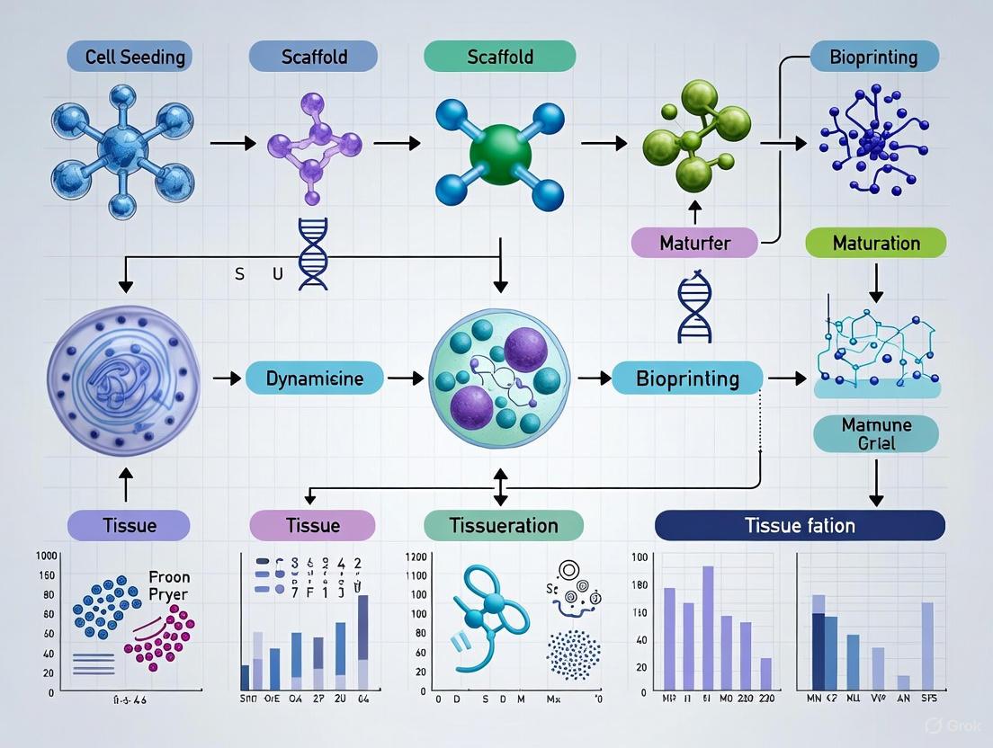
To facilitate understanding of the complex relationships between material properties, processing parameters, and functional outcomes in 4D bioprinting, we provide the following conceptual diagrams created using Graphviz DOT language.
Diagram 1: 4D Bioprinting Workflow for Dynamic Tissue Structures. This diagram illustrates the sequential process from material design through tissue integration, highlighting the central role of smart biomaterials in enabling shape transformation upon stimulus application.
Diagram 2: Classification of Smart Biomaterials for 4D Bioprinting. This diagram categorizes the primary material systems used in 4D bioprinting, showing their hierarchical relationships and specific examples within each category.
The Scientist's Toolkit: Essential Research Reagents and Materials
Successful implementation of 4D bioprinting protocols requires specific research reagents and materials tailored to the unique demands of smart biomaterials. The following table summarizes key solutions and their functions in experimental workflows.
Table 4: Essential Research Reagents for 4D Bioprinting with Smart Biomaterials
| Reagent/Material | Supplier Examples | Key Function | Application Notes |
|---|---|---|---|
| Recombinant Protein Expression System | Novagen (pET plasmids), BLR(DE3) cells | Production of engineered protein polymers with controlled sequences [12] | Enables custom design of protein-based smart materials with specific motifs |
| Tissue Transglutaminase (tTG) | Sigma-Aldrich, Zedira | Enzymatic crosslinking of protein polymers via lysine-glutamine bonds [12] | Critical for forming stable protein hydrogels with controlled mechanical properties |
| Endotoxin Removal Kit | Lonza (QCL-1000), Triton X-114 phase separation | Reduction of endotoxin contamination for improved biocompatibility [12] | Essential for in vivo applications; target <0.1 EU/mL endotoxin levels |
| PEDOT:PSS Conducting Polymer | Heraeus, Sigma-Aldrich | Creating electroactive hydrogels for bioelectronic applications [14] | Enables fabrication of granular hydrogels with electrical conductivity |
| Shape-Memory Polymers (PLA, PGDA) | Polysciences, Sigma-Aldrich | Providing programmable shape transformation capabilities [10] | Select based on transition temperature matching physiological conditions |
| Rheometry Equipment | TA Instruments, Anton Paar | Characterization of flow behavior and mechanical properties [15] | Essential for optimizing printing parameters and predicting in vivo performance |
| Chromogenic LAL Assay Kit | Lonza (QCL-1000) | Quantification of endotoxin levels in biomaterials [12] | Critical quality control measure for materials intended for implantation |
| Bioprinting Compatible Crosslinkers | Sigma-Aldrich, Cellink | Stabilization of printed structures through chemical or physical crosslinking | Select based on cytocompatibility and crosslinking mechanism (UV, ionic, thermal) |
Smart biomaterials—including protein-based polymers, hydrogels, and shape-memory materials—form the foundation of 4D bioprinting for dynamic tissue structures. These advanced materials provide the responsiveness, programmability, and biocompatibility necessary to create tissue engineering constructs that evolve over time, mirroring the dynamic nature of native tissues. The experimental protocols and characterization methods outlined in this document provide researchers with practical frameworks for implementing these materials in their 4D bioprinting research.
As the field advances, future developments will likely focus on creating multi-stimuli responsive materials that can respond to complex biological cues, developing more sophisticated mathematical models for predicting shape transformation behaviors, and addressing the scalability challenges for clinical translation [8]. The integration of computational design, artificial intelligence, and high-throughput screening methods will further accelerate the development of next-generation smart biomaterials with enhanced functionality for regenerative medicine applications.
By leveraging the unique properties of these material systems and following standardized protocols for their processing and characterization, researchers can contribute to the advancing field of 4D bioprinting and develop innovative solutions for complex challenges in tissue engineering and regenerative medicine.
Four-dimensional (4D) bioprinting represents a paradigm shift in biofabrication, introducing time as a dynamic component to create structures that evolve and adapt post-printing [16] [17]. This technology leverages smart, stimuli-responsive biomaterials that react to specific environmental cues—such as temperature, pH, light, magnetic fields, and humidity—by undergoing predictable transformations in shape, properties, or functionality [2] [5]. These dynamic capabilities are crucial for replicating the complex microenvironment of native tissues and enabling advanced applications in tissue engineering, regenerative medicine, and targeted drug delivery [16] [4]. This document provides a detailed overview of these key stimuli-response mechanisms, supported by quantitative data, experimental protocols, and visualization tools, framed within doctoral research on 4D bioprinting for dynamic tissue structures.
The following tables summarize the key characteristics and material systems for the primary stimuli used in 4D bioprinting.
Table 1: Key Characteristics of Stimuli in 4D Bioprinting
| Stimulus | Typical Response Time | Spatial Resolution | Tissue Penetration Depth | Primary Applications in 4D Bioprinting |
|---|---|---|---|---|
| Temperature | Seconds to Minutes [18] | Low to Moderate [2] | Unlimited (Systemic) | Soft tissue engineering, self-fitting implants, drug delivery [2] [4] |
| pH | Minutes to Hours [19] | Moderate (Site-Dependent) | Unlimited (Systemic) | Targeted drug delivery (e.g., tumor microenvironment, GI tract) [2] [19] |
| Light | Milliseconds to Seconds [20] | High (< 50 µm) [20] | Low (UV), Moderate (NIR) [20] | High-resolution patterning, vascular networks, photothermal therapy [20] [5] |
| Magnetic Fields | Milliseconds [21] | Moderate to High | High (Deep tissue) [21] | Remote actuation, robotic surgery, targeted therapy, minimally invasive implants [21] |
| Humidity | Seconds to Minutes [17] | Low to Moderate | Surface Level | Biomimetic self-folding, tubular tissue constructs (e.g., vasculature) [17] |
Table 2: Material Systems and Their Responsive Behaviors
| Stimulus | Material Class | Example Materials | Observed Response/Transformation |
|---|---|---|---|
| Temperature | Shape-Memory Polymers, Thermosensitive Hydrogels | Gelatin Methacrylate (GelMA), Pluronic F-127, Poly(N-isopropylacrylamide) (pNIPAM) [2] [18] [4] | Swelling/contraction, gel-sol transition, shape recovery [18] [4] |
| pH | Ionic Polymers (Polyelectrolytes) | Chitosan, Poly(acrylic acid) (PAA), Alginate, Poly(methacrylic acid) (PMAA) [2] [19] | Swelling/deswelling, degradation, charge reversal, drug release [2] [19] |
| Light | Photopolymerizable/Photothermal Materials | Photosensitive Resins (SLA/DLP), Gold Nanorods, Titanium Nitride Nanoparticles [20] [5] | Photopolymerization (curing), photothermal heating, shape change [20] |
| Magnetic Fields | Magnetic Particle Composites | Ferromagnetic/Paramagnetic Nanoparticles (e.g., Fe₃O₄) dispersed in Polymers/Hydrogels [21] | Bending, twisting, contraction, locomotion [21] |
| Humidity | Hydrophilic Hydrogels | Poly(2-hydroxyethyl methacrylate) (PHEMA), Cellulose-based composites [17] [5] | Swelling-induced bending, self-folding of bilayers into tubes [17] |
Experimental Protocols for Key Stimuli
Protocol: 4D Bioprinting of Thermosensitive GelMA Scaffolds
This protocol details the fabrication of cell-laden scaffolds using a temperature-regulated printhead, a critical requirement for handling thermosensitive bioinks like GelMA [18].
1. Materials and Pre-Printing Setup
- Bioink Formulation: Synthesize or procure GelMA. Prepare a bioink solution of desired concentration (e.g., 5-15% w/v) with a photoinitiator (e.g., 0.5% w/v LAP) in PBS. Keep sterile and store at 4°C until use [18].
- Cell Culture: Expand relevant cell lines (e.g., fibroblasts, mesenchymal stem cells). For bioprinting, trypsinize, count, and resuspend cells to mix with the cold GelMA bioink, achieving a final cell density of 1-10 million cells/mL. Maintain the cell-bioink mixture on ice to prevent premature gelation [18].
- Printhead Calibration: Integrate the temperature-regulated printhead with the bioprinter (e.g., a UR5 robotic arm). Calibrate the PID control system to maintain a stable set temperature (e.g., 15-22°C for GelMA). Validate the temperature stability using an integrated NTC thermistor, targeting a steady-state error of ≤1°C [18].
2. Printing Process
- Parameter Optimization: Load the cold bioink into a sterile syringe and assemble it into the printhead. Allow the bioink to equilibrate to the set temperature for 1-2 minutes. Conduct test prints to optimize parameters: nozzle pressure (15-25 kPa), printing speed (5-15 mm/s), and layer height (150-300 µm) [18].
- Scaffold Fabrication: Print the designed scaffold (e.g., a multilayer lattice) onto a substrate maintained at 37°C or a cooling stage, depending on the material. The temperature-controlled environment ensures consistent viscosity and extrusion, enabling high-fidelity structure formation [18].
- Cross-linking: Immediately after printing each layer, expose the structure to visible or UV light (e.g., 405 nm, 10-20 mW/cm² for 30-60 seconds) to photocrosslink the GelMA and stabilize the shape [18].
3. Post-Printing and Validation
- Maturation: Transfer the printed scaffold to a cell culture incubator (37°C, 5% CO₂) with complete culture medium.
- Viability Assessment: After 1-3 days, assess cell viability using a Live/Dead assay kit. Effective temperature control should yield cell viability >80% [18].
- Structural Analysis: Quantify the structural fidelity of the printed scaffold by comparing its dimensions to the original digital model using microscopy (e.g., digital microscope). Analyze any deformation or shrinkage [18].
Protocol: Imaging-Guided Microscale Photothermal Bioprinting
This protocol leverages light as a stimulus for high-resolution, cell-compatible patterning via a photothermal mechanism [20].
1. System and Bioink Preparation
- Printing System Setup: Assemble an Imaging-Guided Microscale Photothermal Stereolithography Bioprinting (ImPSB) system. This integrates a near-infrared (NIR) laser for photothermal heating, an optical system for real-time imaging, and a digital micromirror device (DMD) for pattern generation [20].
- Photothermal Bioink Formulation: Prepare a composite bioink containing:
- A gel-forming base (e.g., a thixotropic hydrogel).
- Photothermal nanoparticles (e.g., titanium nitride nanoparticles) that convert NIR light to heat.
- A thermal initiator (e.g., ammonium persulfate, APS).
- A thickening agent (e.g., methyl cellulose) to confine the heat spread [20].
- Cell Seeding (Optional): For cell-laden constructs, mix the bioink with cells at an appropriate density, ensuring nanoparticle biocompatibility [20].
2. Printing and Patterning Execution
- Printing Chamber Preparation: Load the bioink into a printing chamber and bring it into focus with the imaging and projection systems.
- Photothermal Patterning: Project defined 2D light patterns from the DMD onto the bioink. The NIR laser (e.g., 980 nm) is simultaneously applied. The nanoparticles in the illuminated regions absorb light and generate localized heat, triggering the initiator and solidifying the bioink in a highly confined volume [20].
- Layer-by-Layer Fabrication: After one layer is printed, the stage or objective moves to deposit the next layer of bioink, and the process repeats to build the 3D structure. Real-time imaging allows for monitoring and potential correction during printing [20].
3. Post-Printing Processing and Analysis
- Rinsing: Gently rinse the printed structure with sterile PBS to remove uncured bioink.
- Cell Culture (if applicable): Transfer the structure to a culture medium and incubate. Monitor cell behavior and viability.
- Resolution Validation: Characterize the resolution of the printed features using scanning electron microscopy (SEM) or confocal microscopy. This system can achieve resolutions finer than a human hair (<50 µm) [20].
Visualization of Stimuli-Response Pathways and Workflows
The following diagrams illustrate the logical workflows and material-response pathways for key stimuli in 4D bioprinting.
Diagram 1: 4D Bioprinting Stimuli-Response Workflow
4D Bioprinting Stimuli-Response Workflow
Diagram 2: Material-Level Response Mechanisms
Material-Level Response Mechanisms
The Scientist's Toolkit: Research Reagent Solutions
Table 3: Essential Materials and Reagents for 4D Bioprinting Research
| Reagent/Material | Function/Application | Example Use-Case |
|---|---|---|
| Gelatin Methacrylate (GelMA) | Thermo- and photo-sensitive hydrogel; serves as a synthetic ECM for cell encapsulation. | Primary bioink for creating soft tissue constructs like cartilage or skin; crosslinks upon exposure to light [18] [4]. |
| Chitosan | Natural pH-responsive polymer (cationic); swells in acidic environments. | Targeted drug delivery to acidic microenvironments, such as tumors or the stomach [2] [19]. |
| Alginate | Ionic-crosslinking polymer; can be modified for pH-sensitivity. | Used in bioprinting for its gentle gelation with calcium ions, often combined with other polymers to enhance functionality [19] [4]. |
| Shape Memory Polymers (SMPs) | Polymers that "remember" a permanent shape and recover upon stimulus (often heat). | Creating self-fitting implants or scaffolds that deploy upon implantation into the body [2] [21]. |
| Magnetic Nanoparticles (Fe₃O₄) | Provide magneto-responsiveness when embedded in hydrogels or polymers. | Enabling remote, non-contact control of printed constructs for actuation or targeted therapy [21]. |
| Photoinitiators (LAP, Irgacure 2959) | Absorb light to generate radicals, initiating photopolymerization of hydrogels. | Crosslinking bioinks during stereolithography (SLA) or digital light processing (DLP) printing [20] [18]. |
| Photothermal Nanoparticles | Convert light energy (e.g., NIR) into localized heat. | Used in photothermal bioprinting to solidify bioinks with high precision or for triggered drug release [20]. |
| N-Isopropylacrylamide (pNIPAM) | Thermosensitive polymer exhibiting a lower critical solution temperature (LCST) near 32°C. | Creating cell sheets or smart valves that expand/contract with temperature changes [2] [5]. |
In the evolving field of tissue engineering, four-dimensional (4D) bioprinting has emerged as a transformative technology that enables the creation of dynamic, cell-laden constructs capable of changing their shape and functionality over time. This stands in contrast to traditional three-dimensional (3D) bioprinting, which produces static structures. The core principles driving these programmed morphological changes are cell traction forces (CTFs) and pre-programmed deformation of smart materials. CTFs are the physical forces generated by cells through their cytoskeletal components, which allow them to pull on and interact with their surrounding environment. In 4D bioprinting, these endogenous cellular forces can be harnessed to direct the self-assembly of printed structures into more complex, tissue-like architectures. Simultaneously, pre-programmed deformation utilizes stimuli-responsive "smart" biomaterials that react to external triggers—such as temperature, pH, or light—by undergoing predictable shape transformations. The convergence of these biological and material-driven mechanisms enables the fabrication of living constructs that can better recapitulate the dynamic nature of native tissues, offering significant potential for advanced applications in regenerative medicine, drug testing, and disease modeling [22] [6].
Fundamental Principles of Shape Change
Cell Traction Forces (CTFs)
Cell traction forces are fundamental to cellular locomotion, tissue organization, and morphogenesis. These forces originate from intracellular actomyosin contractility and actin polymerization, processes that generate mechanical tension transmitted to the extracellular matrix (ECM) or underlying substrate via focal adhesions [6]. In physiological contexts, CTFs play critical roles in wound healing, angiogenesis, and embryogenesis. Within engineered 4D bioprinted systems, these naturally occurring forces can be strategically harnessed to direct the folding and shape evolution of printed scaffolds.
The "cell origami" technique is a prime example of this principle, where CTFs are utilized to cause the self-folding of two-dimensional (2D) patterns into predetermined 3D structures. Research has demonstrated that fibroblasts, such as NIH/3T3 cells, can generate sufficient traction to fold microfabricated plates, successfully creating complex shapes like dodecahedrons that encapsulate other cell types, such as hepatoma cells (HepG2) [6]. This demonstrates the potential of CTFs as a powerful biological driver for the autonomous formation of sophisticated tissue architectures without the need for external mechanical intervention.
Pre-Programmed Material Deformation
Pre-programmed deformation relies on the use of stimuli-responsive or "smart" biomaterials that change their physical properties—such as shape, size, or stiffness—in response to specific environmental cues. These materials form the basis of the 4D effect, enabling predictable transformations from an initial 3D-printed state into a final, more complex configuration.
Table 1: Common Stimuli and Corresponding Smart Materials in 4D Bioprinting
| Stimulus Type | Responsive Material Examples | Mechanism of Action | Key Applications |
|---|---|---|---|
| Temperature | Poly(N-isopropylacrylamide) (PNIPAM), PEO-PPO-PEO triblock copolymers | Polymer chains transition between extended (hydrated) and collapsed (dehydrated) states at a critical temperature. | Rapidly switchable cell culture arrays, dynamic scaffolds [1] [6]. |
| pH | Alginate-based materials, polymers with carboxyl or amine groups | Ionization of functional groups leads to swelling or deswelling due to changes in osmotic pressure and electrostatic repulsion. | Targeted drug delivery to specific physiological environments (e.g., GI tract, tumor microenvironments) [1] [4]. |
| Humidity/Moisture | Hydrogels (e.g., PEG), cellulose-based composites | Absorption or release of water molecules induces volumetric expansion or contraction. | Self-forming tubes for vasculature, programmable scaffolds [1]. |
| Light | Photosensitive polymers (e.g., with LAP photoinitiator) | Light exposure triggers crosslinking or cleavage of chemical bonds, inducing localized strain. | High-precision patterning, remote control of shape change [23]. |
| Magnetic/Electric Fields | Hydrogels doped with conductive polymers (e.g., polypyrrole), carbon nanotubes | Field application generates internal stresses, causing bending, twisting, or swelling. | Bio-actuators, controlled drug release systems [1]. |
The transformation is governed by the intelligent design of the construct, often involving the strategic spatial distribution of multiple materials with different swelling or contraction behaviors. When exposed to a stimulus, these differential properties generate internal stresses that cause the structure to bend, twist, or fold in a pre-determined manner [22]. For instance, a bilayer structure with different swelling capacities will bend upon hydration, much like a bimetallic strip bends upon heating.
Experimental Protocols
Protocol 1: Measuring 3D Traction Forces at the Single-Fiber Scale
Objective: To quantify the 3D traction forces exerted by cells on individual, suspended fibers within a custom-engineered microscaffold [24].
Table 2: Key Reagents and Equipment for 3D Traction Force Measurement
| Item | Function/Description | Example/Details |
|---|---|---|
| Two-Photon Polymerization (TPP) System | Fabricates multilayer arrays of suspended hydrogel fibers with tunable geometry and stiffness. | - |
| Photoresists | Form the scaffold's structural and fiber components. | Resin 1 (anti-adhesive): PEGDA575 + 15% PETA. Resin 2 (cell-adhesive): PEGDA250 + 10% PETA [24]. |
| Fibronectin, CF 640R dye | Coats fibers to promote cell adhesion and enable high-contrast fluorescence imaging. | - |
| Atomic Force Microscopy (AFM) | Characterizes the Young's modulus and stiffness of individual fabricated fibers. | - |
| Confocal or Lattice Light-Sheet Microscope | Captures high-resolution, fast 3D time-lapse images of fiber deformations. | - |
| Cell Lines | Model systems for studying traction forces. | NIH/3T3 fibroblasts, HUVECs, macrophages, dendritic cells [24]. |
Methodology:
- Microscaffold Fabrication:
- Use TPP to print a two-layer array of parallel, suspended fibers. The structural base (walls and carpet) should be printed with anti-adhesive Resin 1, while the deformable fibers are printed with cell-adhesive Resin 2.
- Precisely control fiber spacing (e.g., 5 µm or 10 µm) and mechanical properties by tuning laser power and scanning speed during fabrication.
- Validate the Young's modulus and stiffness of the produced fibers using AFM in force spectroscopy mode.
- Functionally coat the fibers with fibronectin conjugated with a far-red fluorescent dye (e.g., CF 640R).
Cell Seeding and Culture:
- Seed fluorescently labeled cells (e.g., Lifeact-GFP fibroblasts or endothelial cells) onto the fabricated microscaffolds.
- Allow cells to adhere, spread, and exert forces on the fibers for a defined period (e.g., 24 hours) under standard culture conditions.
Image Acquisition:
- Acquire 3D time-lapse images of the cells and the deformed fibers using high-speed confocal or lattice light-sheet microscopy. For highly dynamic immune cells like dendritic cells, lattice light-sheet microscopy is essential to capture short-lived traction events.
Traction Force Calculation:
- Automated Segmentation: Use an automated 3D image analysis framework to segment the geometry of the deformed fibers.
- Finite Element Modeling (FEM): Model the fibers as mechanical objects and use the measured 3D deformations as input.
- Inverse Problem Solving: Apply a regularized inverse method based on FEM to compute the 3D traction forces that caused the observed fiber deflections. A key advantage of this pipeline is that it does not require a stress-free reference state at the end of the experiment, mitigating errors from plastic deformations [24].
Protocol 2: Harnessing Cell Traction Forces for "Cell Origami"
Objective: To leverage the inherent traction forces of cells to self-fold 2D microplates into 2D structures for tissue engineering and co-culture applications [6].
Methodology:
- Fabricate 2D Microplates: Create 2D micropatterned structures using a material that allows for controlled bending. This can involve a thin, enzymatically degradable layer like alginate.
- Cell Patterning:
- Seed two different cell types onto the microplates in a specific pattern. For instance, plate NIH/3T3 fibroblasts (which generate strong CTFs) on the arms of the microplates, and HepG2 hepatoma cells in the central regions.
- Culture the cells for several hours (e.g., 4-28 hours) to allow them to adhere and spread.
- Initiate Self-Folding:
- The traction forces generated by the fibroblasts will generate mechanical stress, initiating the bending of the microplate arms.
- To control the kinetics of folding, add an enzyme like alginate lyase to gradually degrade the alginate layer, reducing its stiffness and allowing the CTFs to dominate.
- 3D Structure Formation: Over time, the microplates will fold into a predetermined 3D structure (e.g., a dodecahedron), with the fibroblasts effectively encapsulating the central hepatoma cells.
- Validation:
- Use confocal microscopy to confirm the final 3D structure and the relative positions of the different cell types.
- Perform live/dead assays over several days to monitor cell viability within the formed constructs.
The Scientist's Toolkit: Essential Research Reagents and Materials
Table 3: Key Reagent Solutions for 4D Bioprinting Research
| Category / Item | Function in 4D Bioprinting |
|---|---|
| Smart Biomaterials | |
| PNIPAM-based Polymers | Temperature-responsive bioinks that gel above their lower critical solution temperature (LCST) ~32°C [1] [6]. |
| Alginate | A versatile biopolymer; its pH-responsive properties and compatibility with divalent cations (e.g., Ca²⁺) make it ideal for ionic crosslinking and drug delivery bioinks [1] [4]. |
| PEGDA (Polyethylene Glycol Diacrylate) | A key photocurable polymer used in vat polymerization. Its modulus and cell adhesiveness can be tuned by varying molecular weight and functionalization [24]. |
| GelMA (Gelatin Methacryloyl) | A widely used photopolymerizable hydrogel that is cell-adhesive and allows for precise stiffness control via UV crosslinking [23]. |
| Crosslinkers & Initiators | |
| LAP (Lithium phenyl-2,4,6-trimethylbenzoylphosphinate) | A biocompatible photoinitiator for UV-mediated crosslinking of hydrogels like GelMA and PEGDA [23]. |
| PETA (Pentaerythritol tetraacrylate) | A crosslinker used to modulate the mechanical properties and anti-adhesiveness of photopolymerizable resins [24]. |
| Characterization Tools | |
| Atomic Force Microscopy (AFM) | Critical for nanoscale mechanical characterization, measuring the Young's modulus of individual fibers and hydrogels [24] [23]. |
| Digital Micromirror Device (DMD) | Enables maskless photolithography for high-resolution, customizable patterning of hydrogel structures, such as microchannels with tunable wall stiffness [23]. |
Workflow and Signaling Visualizations
The following diagram illustrates the integrated workflow of a 4D bioprinting process, combining both material-driven and cell-driven pathways to achieve a final dynamic tissue construct.
Three-dimensional (3D) bioprinting has established itself as a transformative technology in tissue engineering, enabling the fabrication of complex, cell-laden structures through layer-by-layer additive manufacturing [25]. By utilizing bioinks containing living cells, biomaterials, and biological molecules, this approach creates three-dimensional scaffolds that mimic native tissues for applications in regenerative medicine, drug delivery, and disease modeling [26]. However, a significant limitation of conventional 3D bioprinting is its inherent static nature; the fabricated constructs are rigid and cannot recapitulate the dynamic morphological changes that occur in living tissues during development, healing, and normal physiological function [27] [1].
The emergence of four-dimensional (4D) bioprinting addresses this critical limitation by introducing the dimension of time as a fundamental property. Four-dimensional bioprinting is defined as the 3D printing of cell-laden, stimuli-responsive biomaterials that can undergo predefined shape or functionality changes over time in response to specific stimuli [1] [4]. This dynamic capability enables the creation of tissue constructs that more accurately mimic the complex behaviors and adaptive qualities of native tissues, representing a paradigm shift in tissue engineering and regenerative medicine [3] [28].
Comparative Analysis of 3D and 4D Bioprinting Technologies
The transition from 3D to 4D bioprinting builds upon existing bioprinting technologies while incorporating smart materials that respond to environmental cues. The table below summarizes the key bioprinting modalities used in both approaches.
Table 1: Comparison of Bioprinting Technologies Used in 3D and 4D Bioprinting
| Technology | Mechanism | Resolution | Cell Viability | Speed | Advantages | Limitations |
|---|---|---|---|---|---|---|
| Extrusion-Based | Pneumatic or mechanical forcing of bioink through a nozzle [26] | Low to moderate [5] | 40-80% [5] | Fast [5] | High cell density, wide range of material viscosities [1] | Low resolution, potential pressure-induced cell damage [26] |
| Inkjet-Based | Thermal or piezoelectric deposition of small bioink droplets [26] | High (30-40 μm) [5] | >85% [5] | Moderate [5] | High resolution, high cell viability [26] | Low cell density, nozzle clogging [5] |
| Laser-Assisted | Laser energy volatilizes a sacrificial layer, propelling bioink to a substrate [26] | High [5] | >95% [5] | Low to moderate [5] | No nozzle clogging, high cell viability and resolution [26] | High cost, complex setup [5] |
| Stereolithography (SLA) | Photopolymerization of layers using UV laser [26] | High [5] | >85% [5] | Fast [5] | Excellent resolution, smooth surfaces [5] | Limited material options, potential UV cytotoxicity [26] |
The 4D Bioprinting Paradigm: Mechanisms and Material Systems
The fundamental innovation in 4D bioprinting lies in the use of stimuli-responsive biomaterials, often termed "smart materials," which enable dynamic structural changes post-printing. These materials can be programmed to undergo predictable transformations in response to specific internal or external triggers [1] [28].
Stimuli-Responsive Mechanisms
Four-dimensional bioprinting leverages various stimuli to drive structural transformations:
Cell Traction Forces (CTFs): Utilizing the natural contractile forces generated by cells through actomyosin interactions, which can cause printed structures to bend, twist, or curl over several days [3] [27]. This approach harnesses a biologically intrinsic mechanism without requiring external equipment.
Physical Stimuli: Including temperature changes [1], humidity or water immersion [1] [28], light (UV, IR, NIR) [27], and electric [1] or magnetic fields [27]. These typically offer faster shape changes compared to cell-driven approaches.
Chemical Stimuli: Including pH changes [1] and specific enzymes [27], which can trigger structural transformations in particularly sensitive biomaterials.
Table 2: Smart Material Systems for 4D Bioprinting
| Stimulus Type | Material Examples | Response Mechanism | Tissue Applications |
|---|---|---|---|
| Temperature | Poly(N-isopropylacrylamide) (pNIPAM) [1], Polyurethane (PU) [27] | Phase transition (swelling/shrinking) at critical temperature | Drug delivery, soft actuators [1] |
| Cell Traction Forces | Alginate, GelMA, Fibrinogen [3] | Cell-generated contractile forces cause scaffold deformation | Vascular tubes, glandular curvatures, complex tissue shapes [3] |
| Light | GelMA/alginate with poly(dopamine) [27], Gold nanorods [29] | Photothermal effect or photodegradation | Remote-controlled devices, drug delivery [27] |
| Magnetic Field | PLA with Fe₃O₄ nanoparticles [27] | Magnetic particle alignment/attraction | Minimally invasive implants, soft robotics [27] |
| pH | Alginate-based polymers [1], Chitosan [4] | Swelling/shrinking due to protonation/deprotonation | Drug delivery in specific physiological environments [1] |
| Humidity | Cellulose fibrils in acrylamide matrix [1], PEG-based hydrogels [27] | Water absorption/desorption causing swelling/shrinking | Self-assembling structures, adaptive scaffolds [1] |
The following diagram illustrates the decision-making workflow for selecting appropriate stimuli and materials in 4D bioprinting protocol design:
Application Notes: Experimental Protocols for 4D Bioprinting
Protocol 1: 4D Bioprinting Using Cell Traction Forces
This protocol details the methodology for creating shape-changing tissue constructs using cell-generated forces, based on the pioneering work by Ding et al. [3].
Research Reagent Solutions
Table 3: Essential Materials for Cell Traction Force 4D Bioprinting
| Reagent/Material | Function/Purpose | Example Specifications |
|---|---|---|
| GelMA (Gelatin Methacryloyl) | Primary bioink component providing tunable mechanical properties and cell adhesion sites [3] | 5-15% w/v in PBS with 0.5% photoinitiator |
| Photoinitiator | Enables UV crosslinking of bioink | Lithium phenyl-2,4,6-trimethylbenzoylphosphinate (LAP) 0.5% w/v |
| Cells | Source of contractile forces | Human mesenchymal stem cells (hMSCs) or specific tissue cells, passage 3-5, >90% viability |
| Sacrificial Bioink | Cell-free bioink for creating differential contraction zones | Pluronic F127 20% w/v or agarose 2% w/v |
| Culture Medium | Maintains cell viability and function | Cell-specific medium with serum and supplements |
Step-by-Step Procedure
Bioink Preparation:
- Prepare a 10% w/v GelMA solution in PBS containing 0.5% w/v LAP photoinitiator.
- Mix hMSCs (passage 3-5) at a density of 5-10 million cells/mL with the GelMA solution.
- Prepare cell-free sacrificial bioink (20% Pluronic F127) for non-contracting layers.
Printing Process:
- Load cell-laden and sacrificial bioinks into separate printing cartridges.
- Program the bioprinter to deposit alternating layers of cell-laden and cell-free bioinks in the predetermined pattern.
- Apply UV light (365 nm, 5-10 mW/cm²) for 15-30 seconds after each layer to crosslink the GelMA.
Post-Printing Culture:
- Transfer the printed construct to a tissue culture dish with appropriate cell culture medium.
- Maintain at 37°C with 5% CO₂, changing medium every 2-3 days.
- Monitor shape transformation daily using time-lapse microscopy.
Shape Change Analysis:
- Quantify curvature angles using image analysis software.
- Assess cell viability via live/dead staining at days 1, 3, and 7.
- Analyze tissue-specific markers via immunostaining or PCR at predetermined endpoints.
Protocol 2: 4D Bioprinting Using External Stimuli (Temperature)
This protocol describes 4D bioprinting using temperature-responsive smart materials, suitable for creating constructs that change shape upon implantation or exposure to body temperature.
Research Reagent Solutions
Table 4: Essential Materials for Temperature-Responsive 4D Bioprinting
| Reagent/Material | Function/Purpose | Example Specifications |
|---|---|---|
| pNIPAM-based Polymer | Temperature-responsive material with LCST ~32°C [1] | Poly(N-isopropylacrylamide-co-acrylic acid) 10-20% w/v |
| Support Hydrogel | Provides structural integrity during printing | Alginate 3% w/v or Agarose 2% w/v |
| Crosslinking Solution | Stabilizes printed structure | Calcium chloride 100 mM for alginate crosslinking |
| Cells | Biological component for tissue engineering | Cell type specific to application, 5-20 million cells/mL |
Step-by-Step Procedure
Bioink Formulation:
- Prepare pNIPAM-based copolymer solution at 15% w/v in culture-compatible buffer.
- Mix with cells at appropriate density, maintaining temperature below LCST (e.g., 25°C).
- Prepare support bioink (3% alginate) for complex structures.
Printing Setup:
- Maintain printing environment at 20-25°C to prevent premature polymer contraction.
- Use multi-material printing approach to deposit pNIPAM-based bioink and support materials.
- Crosslink support materials immediately after deposition (e.g., with calcium chloride for alginate).
Shape Programming:
- Culture constructs at temperatures below LCST (25-30°C) to maintain expanded state.
- Program final shape by applying mechanical constraints during culture.
Activation and Analysis:
- Activate shape change by raising temperature above LCST (37°C).
- Monitor transformation kinetics using time-lapse imaging.
- Assess cell viability and function post-transformation.
The following diagram illustrates the complete experimental workflow for a 4D bioprinting study:
Technical Considerations and Optimization Strategies
Successful implementation of 4D bioprinting requires careful optimization of multiple parameters:
Bioink Formulation
The composition of bioinks must balance printability, structural integrity, and bioactivity. Key considerations include:
Viscosity Optimization: Bioinks must exhibit shear-thinning behavior for extrusion while maintaining shape fidelity after deposition [5]. Natural polymers like alginate, gelatin, and hyaluronic acid are commonly modified to achieve these properties [26] [4].
Crosslinking Mechanisms: Both physical (ionic, thermal) and chemical (photo-crosslinking, enzymatic) methods are employed, with photo-crosslinkable systems like GelMA providing excellent spatiotemporal control [3] [28].
Biocompatibility: Materials must support cell viability and function throughout the printing process and during shape transformation. Cytocompatible photoinitiators like LAP should be preferred over potentially cytotoxic alternatives [3].
Mathematical Modeling for Shape Prediction
Computational models are increasingly important for predicting the complex shape changes in 4D bioprinted structures. Finite element method (FEM) simulations can model the deformation behavior of multi-material structures by accounting for:
- Swelling/contraction ratios of different bioink components
- Spatial distribution of cell-induced contractile forces
- Mechanical properties of composite materials
- Kinetics of stimulus-responsive behavior
These models enable researchers to design printing patterns that will achieve the desired final 3D structure after transformation [1].
The evolution from 3D to 4D bioprinting represents a significant advancement in tissue engineering, addressing the critical limitation of static constructs by introducing dynamic, time-dependent functionality. By leveraging stimuli-responsive biomaterials and cell traction forces, researchers can now create structures that better mimic the complex behaviors of native tissues.
Future development in 4D bioprinting will likely focus on creating more sophisticated multi-stimuli responsive systems, improving the spatial and temporal control of shape changes, and enhancing the biological functionality of the resulting tissues [4] [29]. As these technologies mature, 4D bioprinting is poised to revolutionize regenerative medicine, drug delivery, and disease modeling by providing dynamic, biomimetic tissue constructs that respond and adapt to their physiological environment.
Methodologies and Applications: Bioprinting Technologies and Dynamic Tissue Engineering
Bioprinting, the use of additive manufacturing to process living cells and biomaterials into 3D structures, has become a pivotal technology in tissue engineering and regenerative medicine [30]. Among the available techniques, extrusion-based bioprinting is the most prevalent, featuring in over half of all bioprinting publications [31]. The emergence of 4D bioprinting introduces "time" as the fourth dimension, enabling the creation of dynamic structures that can change their shape or functionality in response to specific stimuli or inherent cell forces after the printing process [22] [32]. This evolution from static 3D constructs to dynamic 4D tissues allows for better recapitulation of the native in vivo environment, where tissues constantly undergo morphological and functional changes [1]. This application note details the core bioprinting technologies, providing structured comparisons and detailed protocols to guide researchers in selecting and implementing the appropriate method for engineering dynamic tissue structures.
The four primary bioprinting technologies—extrusion-based, inkjet, stereolithography (SLA), and laser-assisted printing—each offer distinct advantages and limitations. Their operating principles are summarized below, followed by a quantitative comparison.
Table 1: Quantitative Comparison of Bioprinting Technologies
| Technology | Typical Resolution | Cell Viability | Print Speed | Key Advantages | Key Limitations |
|---|---|---|---|---|---|
| Extrusion-Based | ≈100 µm [30] | 40-95% (Shear stress-dependent) [30] [33] | Low to Medium | High cell density; Wide range of bioink viscosities; Structural integrity [31] [30] | Lower resolution; Shear stress can damage cells [31] |
| Inkjet | ≈50 µm [1] | >85% [1] | High (Droplet-on-demand) | Low cost; High speed; Good resolution [31] [1] | Low cell density; Nozzle clogging [31] |
| Stereolithography (SLA) | ≈25 µm [31] | >80% (UV light & photoinitiator dependent) [10] | High (Layer-by-layer) | High resolution; Excellent accuracy & surface finish [31] [10] | Limited to photosensitive bioinks; Potential cytotoxicity from UV/photoinitiators [31] |
| Laser-Assisted (LAB) | ≈10 µm [33] | >95% (Nozzle-free) [33] | Very High (Up to 10,000 drops/sec) [33] | Highest cell viability & resolution; No clogging; High cell concentration [33] | High equipment cost; Complex setup [33] |
Detailed Application Notes and Protocols
Extrusion-Based Bioprinting
Application Notes: Extrusion-based bioprinting is highly suitable for creating large, structurally robust tissues, such as bone and cartilage, and is the most common technology used in 4D bioprinting studies [10]. Its compatibility with a wide variety of bioinks, including high-viscosity polymers, makes it ideal for fabricating constructs that can endure post-printing morphological changes. A key innovation in 4D bioprinting using this technology involves leveraging cell-generated contractile forces to drive shape changes in the absence of external stimuli. By patterning cell-laden and acellular bioink layers, researchers can program the construct to bend, twist, or curl over several days as the cells contract the matrix [34].
Protocol: Programming a Self-Morphing Tubular Construct
- Bioink Preparation:
- Printing Process:
- CAD Model Design: Design a multi-layered rectangular sheet with a specific pattern of cellular and acellular regions.
- Printer Setup: Use a pneumatic or piston-driven extrusion system with a maintained stage temperature of 10-15°C to ensure bioink stability.
- Bioprinting: Print the pre-designed pattern, alternating between the cell-laden and acellular bioinks.
- Crosslinking: After deposition, expose the entire construct to UV light (e.g., 365 nm, 5-10 mW/cm² for 30-60 seconds) for photo-crosslinking.
- Post-Printing & 4D Maturation:
- Transfer the crosslinked, flat structure to a tissue-culturing device.
- Culture in standard cell culture medium (e.g., DMEM with 10% FBS).
- The structure will autonomously roll into a tube within 3-7 days due to the contractile forces exerted by the hMSCs in the cellular regions [34].
- Quality Control: Assess cell viability post-printing using a live/dead assay. Monitor shape change over time with time-lapse microscopy.
Inkjet Bioprinting
Application Notes: Inkjet bioprinting is optimal for high-throughput applications requiring moderate resolution, such as creating patterned co-cultures for drug screening or manufacturing thin tissues like skin. Its drop-on-demand nature allows for precise deposition of biomolecules and cells in specific micro-patterns. For 4D applications, it can be used to print osmotically active liposomes or microspheres that release their payload in response to stimuli like temperature or pH changes, enabling controlled drug delivery within a dynamic tissue environment [32].
Protocol: Printing a Stimuli-Responsive Drug Delivery Array
- Bioink Preparation:
- Prepare a bioink containing liposomes loaded with a drug model (e.g., a fluorescent dye) and tuned with two different salt concentrations to create an osmolarity gradient [32].
- Filter-sterilize the bioink to ensure sterility.
- Printing Process:
- Substrate Preparation: Place a sterile glass slide or a hydrogel substrate on the printer stage.
- Printer Setup: Use a thermal or piezoelectric inkjet printhead. Optimize the voltage pulse and frequency to generate consistent droplets.
- Bioprinting: Print a 2D array of the liposome bioink onto the substrate.
- Stabilization: Gently crosslink the printed array if necessary (e.g., vapor crosslinking for alginate-based inks).
- Stimulation & Release:
- To trigger release, expose the array to a specific stimulus (e.g., shift temperature to 37°C or change the pH to 5.5).
- The stimulus disrupts the osmotic balance, causing the liposomes to release their encapsulated contents.
- Analysis: Quantify the release kinetics of the model drug using fluorescence spectroscopy over time.
Stereolithography (SLA) Bioprinting
Application Notes: SLA excels in fabricating constructs with high architectural complexity and smooth surface finishes, which is critical for replicating the fine details of native tissues. In 4D bioprinting, SLA is frequently used with smart, photosensitive polymers. By controlling the spatial distribution of light exposure during printing, it is possible to create internal stress gradients. These pre-programmed stresses are later released by an external stimulus (e.g., warmth), causing the construct to fold into a predetermined 3D shape, such as a self-fitting bone scaffold or a stent [10] [32].
Protocol: Fabricating a Self-Folding Smart Stent
- Bioink/Resin Preparation:
- Printing Process:
- CAD Model Design: Design a flat, 2D pattern that will transform into a tubular stent.
- Printer Setup: Use a digital light processing (DLP) SLA printer. Calibrate the light intensity and exposure time per layer.
- Bioprinting: Print the 2D pattern layer-by-layer. The printing process itself crosslinks the resin and "programs" the temporary flat shape.
- 4D Activation & Shape Change:
- After printing, carefully remove the flat construct from the build platform and rinse.
- To activate the shape change, immerse the construct in a warm saline solution (e.g., 37-45°C, depending on the polymer's transition temperature).
- The construct will autonomously fold and curl into the final, pre-designed 3D stent shape within seconds to minutes.
- Validation: Use optical microscopy to verify the final 3D structure against the designed model. Perform mechanical testing to ensure the stent meets required strength criteria.
Laser-Assisted Bioprinting (LAB)
Application Notes: Laser-Assisted Bioprinting (LAB) is a nozzle-free technique that provides superior resolution and exceptionally high cell viability, making it ideal for engineering highly organized tissue interfaces, such as vascular networks or skin layers, and for printing sensitive cell types. Its precision is invaluable for 4D bioprinting approaches that rely on programming tissue self-organization by placing specific cells in exact initial positions, guiding the subsequent tissue maturation and functional evolution over time [33].
Protocol: Bioprinting a Pre-vascularized Tissue Pattern
- Bioink (Ribbon) Preparation:
- Create a "bioink ribbon" by coating a glass plate (cartridge) with a thin layer of gold or titanium, followed by a layer of a hydrogel (e.g., alginate or collagen) containing the desired cells (e.g., Human Endothelial Cells (hECs)) at a high concentration (up to 100 million cells/mL) [33].
- Printing Process:
- Substrate Preparation: Position a gel substrate (e.g., a Matrigel or fibrin layer) on the receiving stage opposite the ribbon.
- Printer Setup: Use a LAB system with a pulsed laser source (e.g., nanosecond laser).
- Bioprinting: Focus the laser pulses onto the ribbon. The laser energy vaporizes a small portion of the metal layer, generating a bubble that propels a micro-droplet of the cell-laden hydrogel onto the receiving substrate.
- Patterning: By rapidly scanning the laser, print a pre-defined 2D pattern of endothelial cells that will later form capillary-like networks.
- Post-Printing & 4D Maturation:
- After printing, culture the construct in endothelial growth medium.
- Over 7-14 days, the precisely positioned endothelial cells will proliferate, migrate, and self-organize into a nascent 3D vascular network within the surrounding matrix—a 4D process driven by the initial printed pattern.
- Analysis: Confirm the formation of tubular structures using immunostaining for endothelial markers (e.g., CD31) and confocal microscopy.
The Scientist's Toolkit: Essential Reagents for 4D Bioprinting
Table 2: Key Research Reagent Solutions for 4D Bioprinting
| Reagent/Material | Function in 4D Bioprinting | Example Applications |
|---|---|---|
| Methacrylated Gelatin (GelMA) | A widely used photopolymerizable bioink; provides cell-adhesive motifs and allows tuning of mechanical properties for differential swelling or cell-driven shape change [29] [10]. | Vascular grafts, cartilage tissue, self-morphing constructs [34] [10]. |
| Poly(N-isopropylacrylamide) (PNIPAM) | A temperature-responsive polymer; undergoes reversible volume change at its lower critical solution temperature (~32°C), useful for thermal actuation [1]. | Thermally activated actuators and drug delivery systems. |
| Alginate (Sodium Alginate) | A naturally derived polysaccharide; can be ionically crosslinked (e.g., with Ca²⁺); modified to be light or pH-sensitive [22] [32]. | Drug delivery microcapsules, pH-sensitive wound dressings. |
| Poly(ethylene glycol) (PEG) and PEG Diacrylate (PEGDA) | Biocompatible, synthetic polymers; PEGDA is photopolymerizable, forming highly tunable hydrogel networks for high-resolution SLA printing [10] [32]. | Self-folding stents, shape-memory scaffolds. |
| Polylactic Acid (PLA) | A biodegradable, thermoplastic polymer with shape-memory properties; softens when heated, allowing programming of temporary shapes [10]. | 4D printed scaffolds for bone tissue engineering. |
| Gold Nanorods (AuNRs) / Magnetic Nanoparticles (MNPs) | Functional additives; act as transducers converting external energy (e.g., NIR light, magnetic fields) into local heat or mechanical force to trigger shape change [29]. | Magnetically guided microswimmers, light-activated actuators [32]. |
The selection of an appropriate bioprinting technology is paramount for the successful fabrication of dynamic tissue structures. Extrusion-based bioprinting offers versatility for macroscopic structures, while inkjet, SLA, and laser-assisted bioprinting provide progressively higher resolution and cell viability for more complex and delicate tissue architectures. The protocols and reagents outlined herein provide a foundational toolkit for researchers to harness these technologies within the innovative framework of 4D bioprinting. By integrating smart biomaterials and precise cell placement, scientists can program tissue evolution over time, paving the way for advanced models for drug testing, disease modeling, and the future of regenerative medicine.
The evolution of bioprinting from three-dimensional (3D) to four-dimensional (4D) platforms represents a paradigm shift in tissue engineering and regenerative medicine. While 3D bioprinting focuses on creating static structures, 4D bioprinting introduces the dimension of time, enabling the fabrication of dynamic constructs that transform their shape or functionality in response to specific stimuli [8] [4]. This transformative capability allows engineered tissues to better mimic the dynamic nature of native biological environments. At the core of this technology lie stimuli-responsive bioinks—advanced biomaterials that react to environmental cues such as temperature, light, pH, or magnetic fields [35] [5]. The development of these bioinks requires careful balancing of two fundamental properties: printability, which ensures precise fabrication, and biocompatibility, which supports cellular processes and tissue formation. This application note details the essential requirements and methodologies for designing such bioinks within the broader context of creating dynamic tissue structures for research and therapeutic applications.
Fundamental Properties of Stimuli-Responsive Bioinks
Defining Printability and Biocompatibility
For a bioink to be effective in 4D bioprinting, it must simultaneously meet critical criteria in two domains: printability and biocompatibility.
Printability encompasses the rheological and mechanical properties that enable a bioink to be accurately processed through a bioprinter and maintain the intended structure post-fabrication. This includes:
- Structural Fidelity: The ability to maintain shape after deposition without collapsing, often requiring rapid crosslinking mechanisms [5].
- Resolution: The minimum feature size achievable, which is influenced by nozzle diameter for extrusion-based printing and laser spot size for light-based systems [5].
- Shear-Thinning Behavior: A decrease in viscosity under shear stress during extrusion, followed by rapid recovery to prevent diffusion and maintain filament shape [8].
Biocompatibility refers to the bioink's ability to support cellular life and function throughout the printing process and during tissue maturation. Essential aspects include:
- Cell Viability: Maintenance of living cells during and after the printing process, with different printing technologies offering varying viability rates [5].
- Bioactivity: Provision of a supportive microenvironment that facilitates essential cellular processes such as adhesion, proliferation, and differentiation [35] [36].
- Degradation Profile: Controlled breakdown that matches the rate of new tissue formation, ensuring seamless integration with native tissue [35].
Stimuli-Response Mechanisms
Stimuli-responsive bioinks undergo controlled changes in their properties when exposed to specific triggers. The table below summarizes the primary stimuli and their underlying mechanisms.
Table 1: Classification of Stimuli-Responsive Mechanisms in Bioinks
| Stimulus Type | Response Mechanism | Key Material Examples | Typical Application |
|---|---|---|---|
| Physical (Thermal) | Change in polymer hydrophobicity/hydrophilicity at LCST/UCST [37] | Poly(N-isopropylacrylamide) (pNIPAM) [5] | Cell-laden structure deposition |
| Physical (Light) | Photocleavage, photoisomerization, or photopolymerization [35] [37] | Methacrylated gelatin (GelMA), Hyaluronic acid derivatives [35] | Spatiotemporal control of crosslinking |
| Chemical (pH) | Protonation/deprotonation of functional groups causing swelling/collapse [2] [37] | Chitosan, Poly(acrylic acid) [2] | Targeted drug delivery, oral implants |
| Biological (Enzymatic) | Selective cleavage of peptide sequences by specific enzymes [35] | Peptide-crosslinked hydrogels [35] | Cell-mediated remodeling |
| Cell-Generated Forces | Cell contractility exerting mechanical tension on the matrix [34] | Alginate-based composites [34] | Self-morphing tissue constructs |
The following diagram illustrates the decision-making workflow for selecting an appropriate stimulus and material system based on the intended biological application.
Diagram 1: Bioink Selection Workflow for Target Applications
Quantitative Requirements and Material Formulations
Key Parameters for Printability and Biocompatibility
Successful bioink formulation requires meeting specific quantitative targets across physical and biological parameters. The following table consolidates critical data from recent studies to provide benchmark values.
Table 2: Quantitative Requirements for Stimuli-Responsive Bioinks [35] [8] [5]
| Parameter | Target Range | Measurement Technique | Influence on Properties |
|---|---|---|---|
| Viscosity | 10² - 10⁷ mPa·s (shear-thinning) [5] | Rheometer | Extrudability, shape fidelity |
| Storage Modulus (G') | 10² - 10⁴ Pa (post-crosslinking) [8] | Oscillatory rheology | Mechanical integrity, cell signaling |
| Swelling Ratio | 10 - 50 (weight increase %) [35] | Gravimetric analysis | Shape-morphing capability |
| Gelation Time | 5 sec - 10 min [35] | In-situ rheology | Structural fidelity, cell viability |
| Cell Viability | > 80% (post-printing) [5] | Live/Dead assay | Biocompatibility |
| Printability Index | ≥ 0.8 [8] | Filament collapse test | Printing accuracy |
The Scientist's Toolkit: Essential Research Reagents
The table below catalogs key materials and their functions in formulating stimuli-responsive bioinks, as referenced in the literature.
Table 3: Research Reagent Solutions for Bioink Development
| Reagent/Category | Function | Example Materials |
|---|---|---|
| Base Polymers (Natural) | Provide biocompatibility and bioactivity | Alginate, Hyaluronic Acid, Chitosan, Gelatin, Collagen [35] [4] [2] |
| Base Polymers (Synthetic) | Offer tunable mechanical properties and printability | Pluronic, Poly(ethylene glycol) (PEG), Polyacrylamide [5] [37] |
| Stimuli-Responsive Components | Enable dynamic shape or property changes | pNIPAM (thermal), GelMA (light), pH-sensitive monomers [5] [2] [37] |
| Crosslinking Agents | Form the polymer network for stability | Calcium ions (alginate), UV initiators (Irgacure 2959), enzymes (HRP) [35] |
| Bioactive Additives | Enhance cellular response and integration | RGD peptides, growth factors (VEGF, TGF-β), extracellular matrix proteins [35] [36] |
Experimental Protocols
Protocol: Formulating and Characterizing a Light-Responsive GelMA Bioink
This protocol details the synthesis, modification, and characterization of gelatin methacrylate (GelMA), a widely used light-responsive bioink that allows for precise spatiotemporal control via photopolymerization [35].
Materials
- Gelatin (Type A, from porcine skin)
- Methacrylic anhydride (MA)
- Dulbecco's Phosphate Buffered Saline (DPBS)
- Photoinitiator (Irgacure 2959)
- UV light source (wavelength 320-400 nm, intensity 5-20 mW/cm²)
- Dialysis tubing (MWCO 12-14 kDa)
- Lyophilizer
- Rheometer
- UV-Vis Spectrophotometer
Synthesis Procedure
- Gelatin Dissolution: Dissolve 10 g of gelatin in 100 mL of DPBS (10% w/v) at 60°C with continuous stirring until the solution is clear.
- Methacrylation: While maintaining the temperature at 50°C, slowly add 8 mL of methacrylic anhydride (MA) dropwise over 30 minutes. The reaction is pH-sensitive; maintain the pH at 7.4 using 1M NaOH to prevent premature gelling.
- Reaction Continuation: Allow the reaction to proceed for 3 hours at 50°C with continuous stirring.
- Termination and Dialysis: Stop the reaction by diluting the mixture with 200 mL of warm DPBS. Transfer the solution to dialysis tubing and dialyze against distilled water for 7 days at 40°C to remove unreacted reagents and byproducts. Change the water twice daily.
- Lyophilization: After dialysis, freeze the solution at -80°C and lyophilize for 5-7 days to obtain a white, porous foam. Store at -20°C protected from light.
Characterization Methods
- Degree of Substitution (DS)
- Principle: Quantify the percentage of amino groups modified with methacrylate groups using the ninhydrin assay or UV-Vis spectroscopy.
- Procedure: Prepare a 1 mg/mL solution of native gelatin and synthesized GelMA. React with ninhydrin solution and measure absorbance at 570 nm. Calculate DS using the formula: DS (%) = [1 - (AbsorbanceGelMA / AbsorbanceGelatin)] × 100. A typical target DS is 60-80% for optimal mechanical properties and cell viability [35].
Rheological Characterization
- Principle: Assess the viscosity and shear-thinning behavior critical for printability.
- Procedure:
- Prepare a 10% w/v solution of GelMA with 0.5% w/v Irgacure 2959.
- Load the bioink onto a parallel-plate rheometer (25 mm diameter, 0.5 mm gap) at 25°C.
- Perform a flow sweep test, measuring viscosity over a shear rate range of 0.1 to 100 s⁻¹. A successful bioink will show a clear decrease in viscosity with increasing shear rate.
- For gelation kinetics, perform a time sweep at a constant frequency (1 Hz) and strain (1%) while exposing the sample to UV light. Note the time for the storage modulus (G') to surpass the loss modulus (G'').
Printability Assessment
- Principle: Evaluate the bioink's ability to form and maintain stable filaments.
- Procedure:
- Load the bioink into a extrusion bioprinter fitted with a 22G-27G nozzle.
- Print a simple filament into air or a supporting solution.
- Measure the filament diameter and compare it to the nozzle diameter. Calculate the Printability Index (PI) as: PI = Dnozzle / Dfilament. A PI close to 1 indicates high printing fidelity.
- Print a multi-layered grid structure (e.g., 10 mm x 10 mm, 5 layers high) and assess its ability to maintain shape without collapsing.
Protocol: Evaluating Shape-Morphing in Anisotropic Hydrogel Constructs
This protocol describes a method for creating and quantifying the shape-morphing behavior of anisotropic hydrogels, a key phenomenon in 4D bioprinting where flat, printed structures transform into complex 3D shapes over time [35] [34].
Materials
- Two bioinks with different swelling ratios (e.g., high-swelling oxidized alginate and low-swelling GelMA)
- Multi-material extrusion bioprinter
- Crosslinking solution (e.g., CaCl₂ for alginate, UV light for GelMA)
- Incubator or physiological buffer (PBS, 37°C)
- Time-lapse imaging system
- Digital calipers or image analysis software (e.g., ImageJ)
Fabrication and Activation Procedure
- Design and Printing:
- Design a 2D bilayer construct (e.g., 30 mm x 5 mm rectangle) where one layer is the high-swelling bioink and the adjacent layer is the low-swelling bioink.
- Using a multi-material bioprinter, co-print the two bioinks according to the design. Immediately crosslink using the appropriate method for each material (e.g., ionic crosslinking for alginate layer, UV exposure for GelMA layer).
- Induction of Shape Change:
- Carefully detach the printed bilayer structure from the print bed.
- Submerge it in a bath of deionized water or PBS at 37°C to initiate differential swelling.
- Use a time-lapse camera to record the morphing process at 1-minute intervals for 1-2 hours.
Quantitative Analysis
- Bending Angle Measurement:
- Use ImageJ software to analyze the time-lapse images.
- In each frame, draw tangents along the two ends of the curved structure.
- Measure the angle between the tangents. Plot the bending angle versus time to obtain the morphing kinetics.
- Swelling Ratio Quantification:
- Before immersion, measure the dry mass (Mdry) of each layer separately.
- After the shape change has stabilized, carefully separate the layers and measure their wet masses (Mwet).
- Calculate the swelling ratio for each layer as Q = (Mwet - Mdry) / M_dry. The difference in Q between the two layers (ΔQ) is the driving force for the shape morphing.
The following diagram illustrates the experimental workflow for creating and analyzing these anisotropic, shape-morphing constructs.
Diagram 2: Shape-Morphing Construct Analysis Workflow
Concluding Remarks
The strategic design of stimuli-responsive bioinks is foundational to advancing 4D bioprinting for dynamic tissue structures. Success hinges on a multidisciplinary approach that integrates materials science, biology, and engineering principles. The protocols and data outlined herein provide a framework for developing bioinks that not only exhibit excellent printability for fabrication but also possess the sophisticated responsiveness and biocompatibility required to mimic the dynamic nature of native tissues. As the field progresses, future efforts should focus on enhancing the complexity of multi-stimuli responses, improving the longevity and functionality of bioprinted tissues, and addressing the translational challenges of in vivo integration and scalability.
Four-dimensional (4D) bioprinting represents a paradigm shift in regenerative medicine, building upon the foundation of three-dimensional (3D) bioprinting by introducing time as a functional dimension. This advanced manufacturing strategy utilizes stimuli-responsive biomaterials, often called "smart materials," which enable bioprinted constructs to change their shape, properties, or functionality over time in response to specific stimuli [9] [2]. Unlike static 3D-printed structures, 4D bioprinted tissues dynamically morph to better mimic the adaptive nature of native biological tissues [8] [4].
The transformative potential of 4D bioprinting is particularly valuable for engineering complex tissues like bone, cartilage, cardiac, and vascular structures, which require precise anatomical conformations and dynamic functionality [34] [38]. By harnessing various stimulation mechanisms—including physical, chemical, and biological cues—researchers can program tissue constructs to evolve post-implantation, enabling them to integrate more seamlessly with host tissues and respond to changing physiological demands [8] [38].
Bone Tissue Engineering
Application Notes
In bone tissue engineering, 4D bioprinting addresses the critical challenge of creating implants that can adapt to irregular and personalized bone defect sites [38]. The technology leverages shape-memory materials and stimuli-responsive hydrogels that can transform their configuration after implantation, providing better mechanical support and conforming to complex skeletal geometries [38]. A key innovation in this space is the development of constructs that utilize cell-generated contractile forces to drive shape changes, eliminating the need for external stimulation that may be difficult to apply within the body [34].
4D-bioprinted bone structures can be programmed to cross-link or reassemble in response to stimuli, enabling dynamic adaptation to defective areas [38]. Furthermore, these constructs can be designed to support vascular network formation, which is crucial for establishing a biomimetic microenvironment that influences cellular behavior and enhances stem cell differentiation in the post-printing phase [38]. Researchers have successfully demonstrated osteogenic differentiation of bone marrow mesenchymal stem cells within specially formulated bioinks containing silicate nanoplates and chemically conjugated vascular endothelial growth factor to promote vascularization [38].
Experimental Protocol for 4D Bioprinted Bone Constructs
Objective: To fabricate a 4D-bioprinted bone construct with shape-morphing capabilities and osteogenic potential.
Materials:
- Bioink: Gelatin methacryloyl mixed with silicate nanoplates
- Cells: Human bone marrow-derived mesenchymal stem cells
- Stimulus-responsive component: Calcium ions
- 4D Bioprinter: Extrusion-based bioprinting system
- Culture medium: Osteogenic differentiation medium
Methodology:
- Bioink Preparation: Prepare a sterile bioink solution containing 10% w/v GelMA hydrogel, silicate nanoplates, and hBMSCs at a density of 5×10^6 cells/mL.
- Bioprinting: Utilize an extrusion-based bioprinting system to deposit the bioink into a temporary 2D lattice structure at 15°C.
- Shape Transformation: Induce shape memory by exposing the printed structure to Ca2+ ions, then transfer to osteogenic medium at 37°C to trigger transformation into the final 3D configuration.
- Maturation: Culture the transformed constructs in osteogenic medium for 21-28 days, changing medium every 3 days.
- Assessment: Evaluate osteogenic differentiation via alkaline phosphatase staining, calcium deposition, and osteocalcin immunostaining.
Signaling Pathways in Bone Formation
Cartilage Tissue Engineering
Application Notes
Cartilage tissue possesses limited self-repair capacity, making its regeneration a persistent challenge in orthopedics [39]. 4D bioprinting offers promising solutions through the use of smart-responsive systems that can adapt to the dynamic mechanical environment of articular joints [39]. Recent research has focused on magnetic field-responsive bioinks that enable mechanical activation of constructs for enhanced chondrogenesis [40].
Advanced 4D bioprinting strategies for cartilage often incorporate gelatin-based bioinks due to their excellent biocompatibility, tunable properties, and extracellular matrix-mimicking characteristics [39]. These systems have evolved through three distinct developmental phases: foundational materials development, stem cell regulation research, and the emergence of smart-responsive 4D bioprinting technologies [39]. Current approaches leverage stimuli-responsive hydrogels that can change their properties in response to physical cues such as temperature, light, or magnetic fields, providing dynamic microenvironments that promote chondrogenic differentiation and cartilage matrix production [40] [38].
Experimental Protocol for Magnetic 4D Bioprinted Cartilage
Objective: To fabricate shape-morphing magnetic constructs for articular cartilage regeneration.
Materials:
- Bioink: Silk fibroin-gelatin composite with magnetic nanoparticles
- Cells: Human bone marrow mesenchymal stem/stromal cells
- Activation system: External magnetic field generator
- Chondrogenic induction medium
Methodology:
- Magnetic Bioink Formulation: Combine silk fibroin (5% w/v), gelatin (3% w/v), and iron oxide magnetic nanoparticles at 2% w/v concentration. Sterilize before use.
- Cell Seeding: Mix hBMSCs with the bioink at a density of 10×10^6 cells/mL.
- Bioprinting: Print the cell-laden bioink into predetermined patterns using a pneumatic extrusion bioprinter at 20°C.
- Magnetic Actuation: Apply an external oscillating magnetic field (50-100 mT) for 30 minutes daily to mechanically stimulate the constructs.
- Chondrogenic Induction: Culture constructs in chondrogenic differentiation medium for 28 days.
- Analysis: Assess chondrogenesis through sulfated glycosaminoglycan quantification, collagen type II immunohistochemistry, and mechanical property testing.
Research Reagent Solutions for Cartilage Engineering
Table 1: Essential Research Reagents for 4D Bioprinted Cartilage
| Reagent/Material | Function | Example Formulation |
|---|---|---|
| Silk Fibroin-Gelatin Bioink | Provides printable scaffold with tunable mechanical properties | 5% w/v silk fibroin, 3% w/v gelatin |
| Magnetic Nanoparticles | Enables remote actuation and mechanical stimulation | Iron oxide nanoparticles (2% w/v) |
| Chondrogenic Induction Supplements | Promotes stem cell differentiation into chondrocytes | TGF-β3, dexamethasone, ascorbate-2-phosphate |
| Crosslinking Agents | Stabilizes printed constructs | Genipin, microbial transglutaminase |
| Sulfated Glycosaminoglycan Assay Kit | Quantifies cartilage-specific matrix production | Dimethylmethylene blue-based assay |
Cardiac Tissue Engineering
Application Notes
Cardiac tissue engineering faces unique challenges due to the architectural complexity and limited regenerative capacity of the adult myocardium [41] [42]. 4D bioprinting approaches for cardiac applications focus on replicating the structural anisotropy, mechanical responsiveness, and electrical conductivity of native heart tissue [42]. Recent innovations include the development of conductive bioinks that support electromechanical coupling between engineered and native tissues [42].
A significant advancement in this field is the integration of biomimetic design principles with stimuli-responsive materials to create cardiac patches, vascular structures, and chamber-like models that can mature and integrate post-implantation [42]. These constructs often incorporate induced pluripotent stem cell-derived cardiomyocytes to enable patient-specific therapies [42]. The 4D aspect allows these tissues to undergo dynamic remodeling in response to physiological cues, better replicating the adaptive nature of living myocardium [41].
Experimental Protocol for 4D Cardiac Patch
Objective: To create a 4D-bioprinted cardiac patch with electrical conductivity and shape-memory properties.
Materials:
- Bioink: Conductive hydrogel composite (e.g., GelMA with carbon nanotubes)
- Cells: iPSC-derived cardiomyocytes and cardiac fibroblasts
- Electrical stimulation system
- Maturation medium
Methodology:
- Bioink Preparation: Formulate a conductive bioink containing 7% w/v GelMA, 0.5% w/v single-walled carbon nanotubes, and cells at a ratio of 70:30 (cardiomyocytes:fibroblasts).
- Bioprinting: Print the bioink into a predefined 2D sheet pattern using a stereolithography bioprinter.
- Shape Transformation: Transfer the printed construct to 37°C culture conditions, triggering self-folding into a 3D cardiac patch configuration.
- Electrical Maturation: Apply electrical field stimulation (1-2 Hz, 5V/cm) for 7-14 days to promote structural and functional maturation.
- Functional Assessment: Evaluate contractile force, conduction velocity, and calcium handling properties.
Cardiac Development Signaling Pathways
Vascular Tissue Engineering
Application Notes
Vascular tissue engineering benefits tremendously from 4D bioprinting through the creation of dynamic tubular structures that can mimic native blood vessels [34] [4]. Researchers have successfully created tubular and U-shaped constructs using cell-generated forces, where the contractile forces exerted by cells within the bioink drive the morphing process [34]. This approach more accurately mimics natural developmental mechanisms than external stimulation [34].
A key innovation in vascular 4D bioprinting is the development of multi-material systems that can create complex, hierarchical vascular networks with anatomical precision [4]. These systems often employ stimuli-responsive hydrogels that can change their configuration in response to physiological cues, enabling the formation of structures that closely resemble native vasculature in both form and function [34] [4]. The ability to create perfusable vascular networks with embedded functionality represents a significant advancement for tissue engineering overall, as vascularization remains a critical challenge for thick, complex tissues [4].
Experimental Protocol for 4D Vascular Tubing
Objective: To fabricate a 4D-bioprinted vascular conduit using cell-generated forces for shape morphing.
Materials:
- Bioink: Composite hydrogel with tunable crosslinking density
- Cells: Endothelial cells and vascular smooth muscle cells
- Maturation bioreactor with pulsatile flow capability
Methodology:
- Bioink Design: Prepare a dual-bioink system with cell-laden (endothelial and smooth muscle cells) and acellular layers with differential contraction properties.
- Patterned Bioprinting: Alternate cell-laden and acellular bioink layers in a specific ratio and pattern to program directional bending.
- Self-Assembly: Culture the printed sheets in vascular medium for 7-14 days, allowing cell-generated contractile forces to drive rolling into tubular structures.
- Mechanical Conditioning: Transfer tubular constructs to a pulsatile flow bioreactor, gradually increasing flow rate and pressure over 21 days.
- Functional Validation: Assess vessel functionality through permeability studies, contractile response testing, and implantation models.
Quantitative Analysis of 4D Bioprinting Applications
Table 2: Comparative Analysis of 4D Bioprinting Applications Across Tissues
| Tissue Type | Stimulus Mechanism | Key Biomaterials | Transformation Time | Target Cell Types |
|---|---|---|---|---|
| Bone | Cell contractile forces, Ionic crosslinking | GelMA, silicate nanoplates, hydroxyapatite | 3-7 days | Bone marrow mesenchymal stem cells |
| Cartilage | Magnetic field, Temperature | Silk fibroin, gelatin, magnetic nanoparticles | 1-2 hours (actuation) | Chondrocytes, mesenchymal stem cells |
| Cardiac | Electrical stimulation, Temperature | Conductive hydrogels, carbon nanomaterials | 24-48 hours | iPSC-derived cardiomyocytes |
| Vascular | Cell-generated forces, pH | Alginate, gelatin, fibrin | 5-14 days | Endothelial cells, smooth muscle cells |
The Scientist's Toolkit: Essential Research Reagents
Table 3: Core Research Reagent Solutions for 4D Bioprinting Applications
| Category | Specific Reagents | Function in 4D Bioprinting |
|---|---|---|
| Stimuli-Responsive Polymers | Shape-memory polymers, pH-sensitive hydrogels, thermoresponsive polymers | Enable dynamic shape changes in response to specific stimuli |
| Crosslinking Agents | Calcium ions, genipin, microbial transglutaminase | Provide structural integrity and control transformation kinetics |
| Conductive Materials | Carbon nanotubes, graphene, gold nanowires | Facilitate electrical signal propagation in electroactive tissues |
| Bioactive Signals | TGF-β3, BMP-2, VEGF, FGF | Direct stem cell differentiation and tissue maturation |
| Characterization Tools | Sulfated GAG assays, immunohistochemistry kits, mechanical testers | Validate tissue-specific matrix production and functional properties |
The application of 4D bioprinting in bone, cartilage, cardiac, and vascular tissue engineering represents a significant advancement over traditional static approaches. By harnessing stimuli-responsive materials and cell-instructive cues, researchers can create dynamic constructs that better mimic the adaptive nature of native tissues [34] [8] [9]. The protocols and applications detailed in this document provide a framework for developing increasingly sophisticated tissue engineering strategies that can respond to and integrate with the physiological environment.
Future developments in 4D bioprinting will likely focus on enhancing vascularization capacity, improving electromechanical integration, and developing more sophisticated multi-stimuli responsive materials [8] [4] [42]. As the field progresses toward clinical translation, addressing challenges related to scalability, immune compatibility, and long-term stability will be crucial [41] [9]. The integration of computational modeling with experimental approaches will further enhance our ability to predict and control the dynamic behavior of 4D-bioprinted tissues, ultimately leading to more effective regenerative therapies [8].
The emergence of 4D bioprinting represents a paradigm shift in biofabrication, introducing dynamic capabilities that transcend the static nature of traditional 3D models. This technology creates programmable tissue constructs that evolve over time in response to specific stimuli, more accurately mimicking the dynamic human physiology for advanced drug testing and disease modeling [4] [43]. By integrating time as the fourth dimension, researchers can now engineer tissues with shape-memory functionality and adaptive biological responses, offering unprecedented opportunities for pharmacological research and preclinical applications [34] [4]. This Application Note details practical methodologies and experimental protocols for leveraging 4D bioprinting in developing advanced programmable disease models, framed within a thesis investigating 4D bioprinting for dynamic tissue structures.
Fundamental Principles
4D bioprinting extends conventional 3D bioprinting by incorporating time-dependent transformations into biofabricated constructs. While 3D bioprinting focuses on creating static structures with precise spatial control over cells and biomaterials, 4D bioprinting introduces dynamic shape changes or functional evolution in response to specific stimuli [4] [43]. This temporal dimension enables constructs to better mimic native tissue behaviors such as development, homeostasis, and pathological processes.
Stimuli-Responsive Mechanisms
The dynamic capabilities of 4D bioprinted constructs are enabled by several stimulus-response mechanisms, each with distinct applications and material requirements:
- Internal Biological Stimuli: Utilizing intrinsic cell-generated forces, such as cell contractile forces, to drive structural changes without external intervention. This approach more accurately mimics natural developmental mechanisms [34].
- External Physical Stimuli: Employing external energy sources including light, temperature, magnetic fields, or electrical stimulation to trigger predefined transformations in printed structures [4] [43].
- Chemical/Biochemical Stimuli: Responding to changes in pH, ionic strength, or specific biomolecules present in the physiological environment or disease conditions [4].
Table 1: Comparative Analysis of 4D Bioprinting Stimuli-Response Mechanisms
| Stimulus Type | Response Mechanism | Key Advantages | Common Biomaterials | Typical Applications |
|---|---|---|---|---|
| Cell-Generated Forces | Cell contractile forces drive shape changes | Mimics natural development; No external equipment needed | Fibrin, collagen, hyaluronic acid | Tubular structure formation (vessels, airways) |
| Temperature | Polymer expansion/contraction via LCST/UCST transitions | Precise spatial-temporal control; Biocompatible | PLGA, Pluronic F127, gelatin-based polymers | Controlled drug release; Soft tissue models |
| Light | Photocleavage or photoisomerization | High spatiotemporal resolution; Remote activation | Methacrylated gelatin, DLP-based resins | High-resolution patterning; Mechanically tunable constructs |
| Magnetic Fields | Alignment of incorporated magnetic particles | Deep tissue penetration; Remote control | Iron oxide nanoparticle-loaded hydrogels | Remote-controlled constructs; Cardiac tissues |
| pH | Protonation/deprotonation of ionic groups | Responsive to disease microenvironments | Chitosan, alginate, poly(acrylic acid) | Cancer models; Inflammatory disease models |
Experimental Protocols
Protocol 1: Fabrication of Cell-Driven 4D Vascular Constructs
This protocol describes the creation of self-morphing vascular constructs using the intrinsic contractile forces of vascular smooth muscle cells (VSMCs), based on the UIC 4D bioprinting platform [34].
Materials and Equipment
- Bioprinter: Extrusion-based bioprinter with temperature control (4°C-37°C) and pneumatic or mechanical dispensing system
- Bioink A (Cell-laden): Fibrin-based bioink (5-10 mg/mL fibrinogen) containing 5-10 × 10^6 cells/mL human aortic VSMCs
- Bioink B (Acellular): Fibrin-based bioink (5-10 mg/mL fibrinogen) without cells
- Support Bath: 3% (w/v) H-HPMC and 10% (w/v) PF-127 in 1× PBS [44]
- Cell Culture Medium: Smooth muscle cell growth medium with 10% FBS, 1% growth factor supplement, and 1% penicillin-streptomycin
- Maturation Medium: As above, supplemented with 50 µg/mL L-ascorbic acid to promote ECM production
Step-by-Step Procedure
Bioink Preparation:
- Prepare fibrinogen solution at 10 mg/mL in PBS, sterilize by filtration (0.22 µm)
- Mix fibrinogen solution with VSMCs at 5-10 × 10^6 cells/mL, maintaining temperature at 4°C to prevent premature polymerization
- Prepare identical fibrinogen solution without cells for acellular bioink
Printing Configuration:
- Design a alternating layer pattern with CAD software (e.g., 500 µm wide filaments)
- Load support bath into printing chamber and maintain at 18-20°C
- Alternately deposit cell-laden and acellular bioinks through a 22G-27G nozzle (pressure: 15-25 kPa, speed: 5-10 mm/s)
- Print construct dimensions: 15 mm × 15 mm × 2 mm (L × W × H)
Post-Printing Processing:
- Transfer printed construct to differentiation medium
- Incubate at 37°C, 5% CO₂ for 30-60 minutes to initiate fibrin polymerization
- Carefully remove support bath by gentle washing with PBS
4D Maturation:
- Culture constructs for 7-14 days, changing medium every 48 hours
- Monitor shape change daily using time-lapse microscopy
- Constructs typically achieve final curvature within 5-7 days
Quality Control and Assessment
- Cell Viability: Assess using Live/Dead staining (≥80% viability expected)
- Shape Change Quantification: Measure curvature radius using image analysis software
- Contractile Function: Evaluate response to vasoactive agents (e.g., 10⁻⁶ M angiotensin II)
- Tissue Maturation: Analyze ECM deposition via immunohistochemistry (collagen I, elastin)
Protocol 2: VECTOR Platform for Programmable Arterial Models
This protocol details the Voxel-based Embedded Construction for Tailored Orientational Replication (VECTOR) method for creating arterial models with customized contractile and metabolic functions [44].
Materials and Equipment
- Bioprinter: Embedded extrusion bioprinter with precision motion control (≤10 µm positioning accuracy)
- Bioink: Fibrin-based bioink (8 mg/mL fibrinogen, 2 U/mL thrombin) with 10 × 10^6 cells/mL VSMCs
- Support Bath: 3% (w/v) H-HPMC and 10% (w/v) PF-127 in 1× PBS
- Cell Lines: Human aortic vascular smooth muscle cells (VSMCs), human primary aortic endothelial cells (ECs)
- Assessment Reagents: Antibodies for α-SMA, smooth muscle myosin heavy chain, collagen I
Step-by-Step Procedure
Voxel Vector Programming:
- Design arterial architecture with circumferential alignment using CAD software
- Program printing trajectory for omnidirectional deposition to achieve high voxel vector magnitude (VVM)
- Set printing parameters: 21G nozzle, 0.8-1.2 mm/s speed, 20-30 kPa pressure
Embedded Bioprinting:
- Fill printing chamber with support bath, maintain at 20°C
- Print multi-layered tubular structure (1.5-2.0 mm diameter, 10 mm length)
- Vary filament diameter (175-750 µm) to control cellular alignment and VVM
Post-Printing Culture:
- Maintain constructs in perfusion bioreactor with pulsatile flow (1-10 dyne/cm² shear stress)
- Culture for 14-21 days to allow tissue maturation
- For co-culture models, seed endothelial cells in lumen after 7 days
Functional Assessment:
- Measure contractile response to 10⁻⁵ M phenylephrine and 10⁻⁵ M carbachol
- Assess metabolic function via glucose consumption and lactate production
- Evaluate pharmacological responses using standard vasodilators/vasoconstrictors
Key Parameters for Success
- VVM Optimization: Target VVM >0.8 for optimal contractile function
- Filament Diameter: Smaller diameters (175-250 µm) enhance cell alignment
- Matrix Stiffness: Maintain storage modulus (G') of 500-1000 Pa for VSMC differentiation
The Scientist's Toolkit: Research Reagent Solutions
Table 2: Essential Research Reagents for 4D Bioprinting Applications
| Reagent/Category | Specific Examples | Function/Application | Key Considerations |
|---|---|---|---|
| Smart Biomaterials | Shape-memory polymers (PLGA, PCL), thermo-responsive polymers (Pluronic F127), pH-sensitive polymers (chitosan) | Provide stimuli-responsive behavior; Structural support | Biodegradation rate; Mechanical properties; Polymerization mechanism |
| Hydrogel Systems | Fibrin, gelatin-methacryloyl (GelMA), hyaluronic acid, alginate, collagen | Cell encapsulation; Bioink formulation; Mimic native ECM | Gelation mechanism; Ligand density; Stiffness tunability |
| Cell Sources | Primary VSMCs, iPSC-derived cardiomyocytes, endothelial progenitor cells, patient-specific iPSCs | Tissue-specific functionality; Disease modeling; Personalized medicine | Differentiation status; Donor variability; Expansion capacity |
| Support Bath Materials | Carbomer, nanoclay, H-HPMC/PF-127 composites | Enable embedded printing; Maintain structural fidelity during printing | Yield stress; Compatibility with bioinks; Removal post-printing |
| Characterization Tools | α-SMA antibody, live/dead viability assay, RNA-sequencing, traction force microscopy | Assess tissue maturation; Functionality; Molecular profiling | Validation in 3D/4D contexts; Quantification methods; Sensitivity |
Data Presentation and Analysis
Quantitative Assessment of 4D Bioprinted Constructs
Table 3: Performance Metrics of Advanced 4D Bioprinted Disease Models
| Construct Type | Key Functional Metrics | Performance Range | Significance for Drug Testing | Reference Model |
|---|---|---|---|---|
| Cell-Driven Vascular Model | Curvature formation time; Contractile force; ECM protein deposition | 5-7 days to full curvature; 0.5-1.2 mN contraction force; 2.5-fold increase in collagen IV | Enables vascular disease modeling; Drug screening for hypertension | UIC 4D Platform [34] |
| VECTOR Arterial Model | Voxel Vector Magnitude (VVM); Pharmacological response; Metabolic activity | VVM: 0.75-0.95; 60-80% contraction to 10⁻⁵ M phenylephrine; 3.2-fold higher CYP3A4 activity | Predictive toxicology; Metabolic drug interaction studies | VECTOR Technology [44] |
| 4D Bioprinted Liver Model | Albumin production; Urea synthesis; CYP450 activity | 15-25 µg/10⁶ cells/day albumin; 2.8-fold increase in CYP3A4 activity vs. static | Hepatotoxicity screening; Drug metabolism studies | 3D Bioprinted Liver [45] |
| 4D Cardiac Patch | Spontaneous contraction rate; Force generation; Drug response | 0.5-1.5 Hz spontaneous beating; 1-3 mN force; Dose-dependent response to isoproterenol | Cardiotoxicity testing; Cardiovascular drug development | 4D Cardiac Constructs [43] |
Visualization of Workflows and Signaling Pathways
4D Bioprinting Workflow for Programmable Disease Models
Signaling Pathways in 4D Vascular Model Maturation
4D bioprinting technologies represent a transformative approach for creating programmable disease models that dynamically respond to physiological and pharmacological stimuli. The protocols outlined herein for cell-driven vascular constructs and VECTOR arterial models provide researchers with practical methodologies to implement these advanced platforms in drug testing applications. These models demonstrate superior physiological relevance through their adaptive functionalities, enhanced predictive capabilities, and patient-specific applications, potentially reducing the current high attrition rates in drug development. As the field evolves, standardization of quality metrics and validation protocols will be essential for broader adoption in pharmaceutical development pipelines.
Application Notes: Principles and Current Landscape
Four-dimensional (4D) bioprinting represents a paradigm shift in regenerative medicine, introducing the dimension of time to additive manufacturing. It is defined as the 3D printing of cell-laden or biocompatible materials which subsequently undergo predetermined transformations in shape, property, or function in response to specific stimuli [1]. This dynamic capability is pivotal for creating minimally invasive implants that can be deployed in a compact, temporary form and then expand or morph to fit complex defect sites within the body, as well as self-fitting scaffolds that actively adapt to the healing tissue environment [46] [2].
The core mechanism enabling 4D transformation hinges on the use of stimuli-responsive "smart" biomaterials. These materials react to external or internal cues such as temperature, moisture, pH, or light [47] [2]. Furthermore, a novel approach utilizes intrinsic cell-generated forces, where the contractile forces exerted by cells within the bioprinted construct drive the shape change, offering a highly biocompatible alternative to external stimuli [34].
Advantages Over Static 3D Constructs
While 3D-printed constructs are static, 4D bioprinting addresses key clinical challenges:
- Minimally Implantation: Enables the printing of compact, temporary shapes that can be implanted through smaller incisions, reducing surgical trauma [46].
- Self-Adaptation: Allows constructs to dynamically conform to irregular tissue boundaries, improving integration and mechanical stability [46] [48].
- On-Demand Functionality: Facilitates the regulation of cell fate and tissue regeneration in different healing stages by controlling the scaffold's microenvironment over time [46].
The following tables summarize key quantitative data from recent advancements in 4D bioprinting for tubular and self-fitting structures.
Table 1: 4D-Printed Shape-Changing Scaffolds for Tubular Structures
| Application | Material Composition | Fabrication Method | Stimulus | Key Quantitative Results | Reference |
|---|---|---|---|---|---|
| Vascular Graft | Sodium Alginate, Collagen Peptide, Endothelial Progenitor Cells | Coaxial Extrusion | Ionic Cross-linking | Lumen of 3–3.5 mm, matching saphenous vein biomechanics. | [48] |
| Tracheal Stent | Methacrylated Polycaprolactone (PCL) | Digital Light Processing (DLP) | Thermal (Body Temp) | High resolution (50 µm), fast shape recovery (<10 s), ~95% recovery ratio. | [48] |
| Bifurcated Stent | Polyurethane | FDM with Kirigami Geometry | Thermal (50–60 °C) | Compact delivery shape, expands to bifurcated form in <8 seconds. | [48] |
| Nerve Conduit | Alginate (Alg) and Methylcellulose (MC) | Extrusion-based 3D Printing | Aqueous Medium (37°C) | Rapid self-closing folding (<10 s), enables sutureless neurorrhaphy. | [48] |
Table 2: 4D-Printed Nerve Guidance Conduits with Thermal Activation
| Material | Fabrication Method | Stimulus | Tube Diameters | Shape Recovery Time | Key Feature | |
|---|---|---|---|---|---|---|
| Poly(lactide-co-trimethylene carbonate) (PLATMC) | Electrospinning & Thermal Programming | Thermal (37–40 °C) | Small: 0.6 mm, Large: 2 mm | 12 s (small), 25 s (large) | Multichannel conduit mimicking nerve fascicles for oriented axonal regeneration. | [48] |
Experimental Protocols
Protocol 1: 4D Bioprinting of Cell-Driven Self-Morphing Constructs
This protocol leverages cell-generated contractile forces to achieve complex shapes, eliminating the need for external stimuli [34].
1. Bioink Preparation:
- Formulate a primary bioink using a biocompatible hydrogel such as gelatin methacryloyl (GelMA) or a similar collagen-based material.
- Incorporate the desired living cells (e.g., mesenchymal stem cells) into the hydrogel matrix at a high density to ensure sufficient contractile force generation.
- Prepare a secondary bioink, which is an acellular version of the same hydrogel.
2. 3D Bioprinting with Patterned Layers:
- Utilize a extrusion-based bioprinter.
- Design the print path to arrange layers in specific patterns, such as bilayers or grids, alternating between the cell-laden and acellular bioinks.
- The differential contraction between cellular and acellular regions is the key programming parameter.
- Print the structure into a temporary, maintenance-friendly shape.
3. Post-Printing Culture and Morphogenesis:
- Transfer the printed construct to a standard tissue culture environment.
- Over 1-7 days, the cell-laden regions will contract due to inherent cell forces.
- This differential contraction between adjacent layers generates internal stresses, causing the entire structure to bend, twist, or curl into a pre-designed complex shape (e.g., tubes, U-shapes, spirals).
- Monitor the shape change and culture until the desired permanent form is stable.
Protocol 2: 4D Printing of Self-Fitting Bone Implants with Thermal Activation
This protocol details the creation of a shape-memory polymer-based bone implant that activates upon implantation [46] [47].
1. Material Synthesis and Bioink Loading:
- Select a biodegradable shape memory polymer (SMP) such as methacrylated polycaprolactone (PCL) or a composite like chitosan-PLA.
- Program the SMP's temporary shape by heating it above its transition temperature (e.g., glass transition temperature, Tg, or melting temperature, Tm), deforming it into a compact shape, and cooling under constraint.
- For bioactive implants, load the polymer with osteogenic factors (e.g., Bone Morphogenetic Protein-2) or stem cells prior to printing.
2. 3D Printing of the Temporary Shape:
- Employ a suitable printing technique such as Digital Light Processing (DLP) for high resolution or Fused Deposition Modeling (FDM) for thermoplastics.
- Print the implant directly in its pre-programmed, compact temporary shape.
3. Implantation and Shape Recovery:
- Perform a minimally invasive surgical procedure to implant the compact scaffold.
- Upon exposure to the body's temperature (~37°C), the SMP will trigger its shape memory effect.
- The implant will expand or unfold to its pre-designed, permanent shape, conforming to the contours of the bone defect.
- The recovery is typically fast, occurring within seconds to minutes.
Workflow Visualization
The following diagram illustrates the logical workflow and decision points for selecting the appropriate 4D bioprinting protocol based on the target application.
The Scientist's Toolkit: Research Reagent Solutions
Table 3: Essential Materials for 4D Bioprinting Research
| Reagent/Material | Category | Function in 4D Bioprinting | Example Use-Cases |
|---|---|---|---|
| Gelatin Methacryloyl (GelMA) | Photocrosslinkable Hydrogel | A versatile bioink that supports cell encapsulation; its stiffness and swelling can be tuned by crosslinking. | Cell-driven morphogenesis [34], vascularized tissues [47] [49]. |
| Methacrylated PCL | Shape Memory Polymer (SMP) | Provides a rigid, yet biodegradable structure with thermally-induced shape memory for self-fitting implants. | High-resolution tracheal stents, bone scaffolds [48]. |
| Alginate-Methylcellulose Blend | Ionic Cross-linkable Hydrogel | Swells in aqueous environments; used for rapid self-folding or self-closing structures due to differential swelling. | Sutureless nerve conduits [48]. |
| Poly(lactide-co-trimethylene carbonate) (PLATMC) | Biodegradable Elastomer | Combines flexibility with shape-memory properties; suitable for soft tissue supports that require cyclic movement. | Multichannel nerve guidance conduits [48]. |
| Chitosan | pH-Sensitive Polymer | Swells and changes properties in acidic environments; used for targeted drug delivery or gastric applications. | Composite scaffolds for enhanced cell adhesion [47] [2]. |
| Poly(N-isopropylacrylamide) (PNIPAM) | Temperature-Responsive Polymer | Undergoes a volume phase transition near body temperature, useful for actuators and controlled release. | Thermally active valves or drug delivery systems [1]. |
| Lithium Phenyl-2,4,6-trimethylbenzoylphosphinate (LAP) | Photoinitiator | Enables rapid crosslinking of hydrogels under visible or UV light in cytocompatible conditions. | Crosslinking GelMA and other photopolymerizable bioinks [49]. |
Overcoming Challenges: Material, Fabrication, and Biocompatibility Hurdles
In the evolving field of 4D bioprinting for dynamic tissue structures, the triad of material limitations—biocompatibility, degradation rates, and mechanical integrity—presents a critical frontier for research and development. Four-dimensional bioprinting introduces the dimension of time, enabling fabricated constructs to change shape or functionality in response to external stimuli such as temperature, pH, light, or magnetic fields [8] [22]. This dynamic capability holds immense promise for creating tissues that more accurately mimic the native healing and adaptive processes in vivo. However, the smart biomaterials that enable these transformations must simultaneously satisfy stringent biological and mechanical requirements. Their biocompatibility must ensure cell viability and function, their degradation kinetics must synchronize with tissue regeneration without producing harmful byproducts, and their mechanical properties must provide initial support while adapting to dynamic physiological environments [50] [51]. This application note details standardized protocols for evaluating these key material properties, providing a framework for researchers to advance the development of safe and effective 4D-bioprinted tissues.
Quantitative Comparison of Biomaterials for Bioprinting
The selection of base materials and their subsequent processing significantly influence the final properties of a bioprinted construct. The following tables summarize key performance metrics for metals and polymers relevant to the biofabrication field.
Table 1: Mechanical and Degradation Properties of Biodegradable Metals
| Material Class & Specification | Yield Strength (MPa) | Ultimate Tensile Strength (MPa) | Elongation at Break (%) | Corrosion Rate (mm/year) | Key Applications & Limitations |
|---|---|---|---|---|---|
| Mg Alloy (Mg-0.3Sr-0.4Mn) [52] | 205 | 242 | Data Not Provided | 0.39 | Orthopedic fixation; optimal balance of strength and corrosion. |
| Mg Alloy (WE43, processed) [50] | >250 | Data Not Provided | Data Not Provided | 0.2 - 0.5 | Load-bearing orthopedics; challenge is gas evolution. |
| Zn Alloy (Zn-0.1Mg-1Nd) [53] | Data Not Provided | 381 | 17.7 | 0.094 | Orthopedic applications; excellent strength and slow degradation. |
| Porous Fe (Gyroid Scaffold) [54] | Data Not Provided | Data Not Provided | Data Not Provided | Data Not Provided | Bone substitutes; maintains mechanical integrity during degradation. |
Table 2: Properties of Polymer Classes Used in 4D Bioprinting
| Material Class | Example Materials | Key Stimuli | Typical Modulus | Primary Advantages | Key Limitations |
|---|---|---|---|---|---|
| Hydrogels [8] [51] | Alginate, Chitosan, Collagen | pH, Temperature, Humidity | ~kPa - 100 kPa | High biocompatibility, cell encapsulation | Slow response, low mechanical strength |
| Shape Memory Polymers (SMPs) [8] [51] | Specific Polyesters, Polyurethanes | Temperature, Light | ~MPa - GPa | Faster response, higher strength | Potential cytotoxic degradation |
| Self-Healing Materials [8] | Specific Hydrogels, Polymers | Damage, pH | Varies | Structural recovery, enhanced longevity | Complex synthesis and formulation |
Experimental Protocols for Material Evaluation
Protocol: In Vitro Degradation and Ion Release Profiling
This protocol assesses the degradation behavior of metallic alloys and the release kinetics of their ions, which is critical for predicting in vivo performance and biocompatibility.
I. Materials and Equipment
- Test Specimens: Polished alloy discs (e.g., Ø10 mm x 2 mm) or 3D-printed scaffolds.
- Solution: Simulated Body Fluid (SBF), prepared according to standard formulations (e.g., Kokubo recipe).
- Equipment: Sterile centrifuge tubes, analytical balance (±0.1 mg), CO₂ incubator maintained at 37°C, pH meter, inductively coupled plasma mass spectrometry (ICP-MS) system.
- Consumables: Chromic acid (200 g L⁻¹) for corrosion product removal [53].
II. Experimental Procedure
- Initial Measurement: Precisely weigh each specimen (W₀) and record initial dimensions.
- Immersion Setup: Place each specimen in a separate centrifuge tube with SBF, ensuring a consistent solution volume-to-sample surface area ratio (e.g., 20 mL cm⁻²) [53]. Incubate at 37°C.
- Time-Point Sampling: Remove samples (in triplicate) at predetermined intervals (e.g., 1, 3, 7, 14, 28 days).
- Solution Analysis: At each time point, collect and store the immersion solution for ICP-MS analysis to quantify released metal ions (e.g., Mg²⁺, Sr²⁺, Zn²⁺).
- Specimen Processing: Rinse retrieved specimens with deionized water.
- For corrosion rate analysis: Immerse in chromic acid to remove corrosion products, rinse again, dry thoroughly, and weigh (W₁) [53].
- For surface analysis: Image the corroded surface via SEM without removing products.
III. Data Analysis
- Corrosion Rate (CR): Calculate using the mass loss equation: ( CR = (K \times \Delta W) / (A \times T \times \rho) ), where K is a constant, ΔW is mass loss (W₀ - W₁), A is surface area, T is immersion time, and ρ is density [53].
- Ion Release: Plot ion concentration versus time to establish release profiles.
- Surface Morphology: Document changes in surface topography and corrosion pit formation via SEM.
Protocol: Cytocompatibility and Osteogenic Potential Assessment
This protocol evaluates the biological safety and bone-forming potential of material extracts or direct contact with cells, using established cell lines.
I. Materials and Equipment
- Test Material: Sterile material extracts (prepared by incubating material in cell culture medium for 24-72 hours) or sterile material discs.
- Cells: Human Bone Marrow-derived Mesenchymal Stem Cells (hBMSCs) or murine pre-osteoblasts (e.g., MC3T3-E1).
- Reagents: Cell culture medium (e.g., α-MEM), fetal bovine serum (FBS), penicillin-streptomycin, AlamarBlue or MTT reagent, Live/Dead assay kit (e.g., calcein-AM/ethidium homodimer-1), osteogenic differentiation medium (ascorbic acid, β-glycerophosphate, dexamethasone), Alkaline Phosphatase (ALP) staining kit.
- Equipment: Cell culture incubator (37°C, 5% CO₂), fluorescence/absorbance microplate reader, inverted fluorescence microscope.
II. Experimental Procedure
- Cell Seeding: Seed hBMSCs at a standard density (e.g., 10,000 cells/cm²) in culture plates.
- Treatment:
- Extract Method: Replace medium with material extract (e.g., 50% concentration) or pure medium (control) [54].
- Direct Contact: Place sterile material discs into wells after cell adhesion.
- Cell Viability (Day 1-3):
- Metabolic Activity: Use AlamarBlue assay according to manufacturer's instructions. Measure fluorescence/absorbance. Cell viability >90% is considered excellent [52] [54].
- Live/Dead Staining: At set time points, incubate cells with calcein-AM (labels live cells green) and ethidium homodimer-1 (labels dead cells red). Image with a fluorescence microscope.
- Osteogenic Differentiation (Day 7-14):
- ALP Activity: After 7-14 days in osteogenic medium, fix cells and stain for ALP, an early osteogenic marker. Quantify activity via a pNPP assay or image staining. A 2.46-fold increase, as seen in Mg-Sr-Mn alloys, indicates strong osteogenic induction [52].
IV. Data Interpretation
- High cell viability (>90%) and predominantly green fluorescence in Live/Dead staining indicate good cytocompatibility.
- Elevated ALP activity and mineralization nodules confirm enhanced osteogenic differentiation.
Essential Diagrams for Material-Cell Interaction and Testing
Material Properties Interrelationship in 4D Bioprinting
This diagram visualizes the interconnected relationship between the three core material properties and their collective impact on the success of a 4D-bioprinted construct.
Degradation Testing Workflow
This flowchart outlines the key steps in the standardized protocol for evaluating material degradation and its biological effects.
The Scientist's Toolkit: Research Reagent Solutions
Table 3: Essential Materials for Evaluating Material Limitations
| Category | Item | Function & Application Notes |
|---|---|---|
| Base Materials | Mg-Sr-Mn Alloys [52] | Ideal for orthopedic 4D scaffolds; provides a balance of strength, controlled degradation, and osteogenic properties (evidenced by 2.46x higher ALP activity). |
| Zn-Mg-Nd Alloys [53] | Suited for applications requiring high tensile strength (~380 MPa) and very slow corrosion (~0.1 mm/year). | |
| Stimuli-Responsive Hydrogels (e.g., Alginate, Chitosan) [8] [51] | Enable 4D shape-morphing; respond to pH, temperature, or ions for dynamic structure formation. | |
| Cell Culture | hBMSCs [53] | Primary human cells for evaluating cytocompatibility and osteogenic differentiation potential. |
| MC3T3-E1 Pre-osteoblasts [52] | Murine cell line widely used for standardized screening of osteogenic activity. | |
| Osteogenic Medium Supplements (Ascorbic acid, β-glycerophosphate, Dexamethasone) | Induces osteoblast differentiation; essential for testing the bioactivity of materials. | |
| Key Assays | AlamarBlue / MTT Assay [52] [54] | Quantifies metabolic activity as a proxy for cell viability and proliferation. |
| Live/Dead Staining Kit (Calcein-AM/ETH-1) | Provides a direct visual assessment of live (green) and dead (red) cells on material surfaces. | |
| Alkaline Phosphatase (ALP) Kit [52] | Measures the activity of a key early osteogenic marker, either by biochemical assay or histochemical stain. | |
| Characterization | Inductively Coupled Plasma Mass Spectrometry (ICP-MS) | Precisely quantifies the concentration of specific metal ions released during material degradation. |
| Scanning Electron Microscope (SEM) [52] [53] | Characterizes surface morphology, grain structure, and corrosion features at high resolution. |
Application Note: Multi-Material Integration in 4D Bioprinting
Core Challenge and Principle
The integration of multiple smart materials is fundamental to creating complex, dynamic tissue constructs in 4D bioprinting. The core challenge lies in the precise spatial arrangement of materials with distinct, often incompatible, stimuli-responsive properties within a single, cohesive print. Success hinges on orchestrating a bottom-up assembly where heterogeneous building blocks are engineered to self-assemble into larger, functional tissue architectures [55]. This approach aims to replicate the native tissue microenvironments that are critical for directing cell fate and achieving desired dynamic functionalities such as shape morphing or programmed degradation [55].
Key Methodologies and Enabling Technologies
Microfluidic Bioprinting: This is a premier technology for achieving high-fidelity multi-material integration. Microfluidic printheads, or "printhead-on-a-chip" systems, allow for real-time switching, mixing, and coaxial deposition of different bioinks [55].
- Capabilities: Enables the fabrication of core-shell filaments for vascular-like structures, gradient bioinks for mimicking tissue interfaces, and intricate multi-cellular patterns.
- Mechanism: Laminar flow within microchannels permits the side-by-side flow of different bioinks without turbulent mixing, enabling precise deposition. Coaxial nozzles allow one material to be seamlessly sheathed by another [55].
Extrusion-Based Multi-Material Printing: Advancements in extrusion-based systems now allow for the use of multiple printheads, each loaded with a different smart material.
- Challenge: Different thermoplastics or hydrogels may require different printing temperatures and pressures, making process synchronization complex [5].
- Solution: The development of novel, compatible material combinations and sophisticated printer control software is key. For instance, combining a moisture-responsive polymer like poly(2-hydroxyethyl methacrylate) (pHEMA) with a temperature-responsive polymer like poly(N-propylacrylamide) (pNIPAM) allows for the creation of structures that respond to multiple stimuli [5].
Vat Polymerization for Multi-Material Structures: While traditionally single-material, innovations in DLP and SLA are enabling multi-material printing.
- Method: Techniques involve washing and resin-swapping between layers or using sophisticated vats with fluidic systems to switch photopolymer resins, creating objects with spatially controlled mechanical properties [56].
Experimental Protocol: Microfluidic Coaxial Bioprinting of a Vasculature-Mimetic Construct
Objective: To fabricate a cell-laden, hollow tubular structure mimicking a blood vessel using a coaxial microfluidic printhead.
Materials:
- Bioink A (Core): A low-viscosity, cell-laden bioink (e.g., gelatin methacryloyl (GelMA) with endothelial cells).
- Bioink B (Sheath): A high-viscosity, crosslinkable biopolymer (e.g., sodium alginate).
- Crosslinking Solution: Calcium chloride (CaCl₂) solution.
- Equipment: Bioprinter equipped with a coaxial microfluidic nozzle; sterile syringes and tubing.
Procedure:
- Bioink Preparation: Prepare Bioink A and B according to standardized protocols, ensuring sterility. Keep Bioink A on ice to maintain low viscosity until printing.
- Printer Setup: Load Bioinks A and B into separate syringes. Connect the syringes to the respective inlets of the coaxial nozzle. The nozzle should be designed so that Bioink B (sheath) flows through an outer annular channel and Bioink A (core) flows through a central channel.
- Printing Parameters Calibration:
- Optimize the flow rates (
Q_coreandQ_sheath) using the printer's software to achieve a stable, concentric filament. - Set the printing speed to match the total extrusion rate.
- Position the nozzle tip at a defined height (e.g., 1-2 mm) above a substrate immersed in or coated with the CaCl₂ crosslinking solution.
- Optimize the flow rates (
- Printing and Crosslinking:
- Initiate simultaneous extrusion of both bioinks.
- As the composite filament is deposited into the CaCl₂ bath, the alginate in the sheath layer undergoes instantaneous ionic crosslinking, forming a stable hollow tube.
- Program the bioprinter to fabricate a tubular structure in a predefined pattern (e.g., a straight tube or a simple branched network).
- Post-Printing Processing: After printing, transfer the construct to a cell culture medium. The GelMA core may be further crosslinked via UV light if required by the specific bioink formulation.
Table 1: Quantitative Parameters for Coaxial Bioprinting
| Parameter | Typical Range | Function |
|---|---|---|
Core Flow Rate (Q_core) |
2-5 µL/min | Controls lumen diameter and cell density in the core. |
Sheath Flow Rate (Q_sheath) |
10-20 µL/min | Determines wall thickness and structural integrity. |
| Nozzle Standoff Height | 1-3 mm | Affects filament spreading and crosslinking initiation. |
| Crosslinking Bath [CaCl₂] | 50-200 mM | Governs crosslinking density and gelation speed. |
| Printing Speed | 5-15 mm/s | Must be synchronized with total extrusion rate. |
Application Note: Resolution in 4D Bioprinting
Core Challenge and Principle
Resolution in 4D bioprinting refers to the smallest achievable feature size and the dimensional accuracy of the deposited material, critically impacting the mechanical properties and biological functionality of the final construct [57]. The challenge is twofold: achieving high initial printing resolution and ensuring that the post-stimulus, 4D transformation occurs in a predictable and high-fidelity manner. In extrusion-based bioprinting—the most common method for 4D—low spatial resolution is a significant limitation, often caused by poor feedback control, material properties, and printing parameters, leading to deviations from the intended design [57].
Key Methodologies and Enabling Technologies
Vision-Based Real-Time Path Compensation: This advanced technique uses computer vision to dramatically improve printing accuracy.
- Principle: An industrial camera captures the bioprinted object after each layer. Image processing algorithms extract the centerline of the printed filament and compare it to the reference path. The resulting error data is used to generate a compensated robot path for subsequent layers [57].
- Efficacy: This method can reduce the average printing error for curved filaments from 12.7 mm² to 7.0 mm² and minimize layer width disparity to 0.15 mm compared to 0.6 mm in traditional methods [57].
Advanced Printing Modalities: The choice of printing technology inherently defines the resolution limits.
- Inkjet Printing: Offers high resolution (30-40 µm) and high cell viability (>85%), but is limited by low bioink viscosity and cell density [5].
- Stereolithography (SLA) & Digital Light Processing (DLP): These vat polymerization techniques provide the highest resolution and smooth surface finishes, suitable for intricate microfluidic devices and tissue constructs [5] [56]. DLP, in particular, can achieve rapid printing by curing entire layers at once [56].
- Extrusion-Based Printing: While versatile, its resolution is limited by nozzle diameter (typically 100-200 µm) and is prone to structural deformation with soft materials [5].
Material-Driven Strategies: The bioink itself is a critical factor.
- Shear-Thinning Bioinks: These materials exhibit high viscosity at rest, maintaining shape after extrusion, but thin under shear stress within the nozzle, enabling smooth extrusion [58].
- Support Baths: Techniques like Freeform Reversible Embedding of Suspended Hydrogels (FRESH) use a yield-stress support bath to hold the bioink in place during printing, allowing for the fabrication of complex, overhanging structures that would otherwise collapse [57].
Experimental Protocol: Vision-Based Path Compensation for a Curved Filament
Objective: To improve the printing accuracy of a complex curved structure by implementing a closed-loop, vision-based tool path compensation system.
Materials:
- Equipment: Robotic arm-based bioprinter; high-resolution industrial camera mounted with a fixed field of view; computer with image processing software (e.g., OpenCV).
- Bioink: A suitable hydrogel with contrast for clear imaging (e.g., collagen, alginate).
Procedure:
- System Calibration:
- Calibrate the camera to the robot's coordinate system to ensure accurate mapping between the captured image and the robot's spatial position.
- Reference Path Printing:
- Program the robot with the original reference path (G-code) for the first layer of the curved structure.
- Print the first layer.
- Image Acquisition and Processing:
- After printing the layer, the camera captures a top-down image of the printed filament.
- Use image processing algorithms to:
- Convert the image to grayscale and apply a threshold to create a binary image.
- Apply a skeletonization algorithm to extract the centerline of the printed filament.
- Convert this centerline into a set of spatial coordinates.
- Error Calculation and Path Compensation:
- Computationally compare the extracted centerline coordinates with the original reference path.
- Calculate the spatial deviation (error) at multiple points along the path.
- Generate a new, compensated robot path for the next layer by adjusting the original path to counteract the measured error.
- Iterative Printing:
- The robot prints the next layer using the newly generated, compensated path.
- Repeat steps 3-5 for each subsequent layer to continuously minimize deviation throughout the printing process.
Table 2: Resolution and Performance of Bioprinting Technologies
| Printing Technology | Typical Resolution | Cell Viability | Key Limiting Factors |
|---|---|---|---|
| Extrusion-Based | 100 - 200 µm [5] | 40-80% [5] | Nozzle diameter, shear stress, bioink viscosity. |
| Inkjet | 30 - 40 µm [5] | >85% [5] | Bioink viscosity, nozzle clogging. |
| Stereolithography (SLA) | High (µm scale) [5] | >85% [5] | UV light penetration, resin biocompatibility. |
| Laser-Assisted | High (µm scale) [5] | >95% [5] | Equipment cost, complexity. |
| Vision-Guided Robotic | ~150 µm layer width error [57] | N/A (Method dependent) | Computational complexity, lighting conditions. |
Application Note: Scalability in 4D Bioprinting
Core Challenge and Principle
Scalability refers to the ability to fabricate biologically functional tissue constructs that are clinically relevant in size, most critically requiring the integration of vascular networks to support nutrient and waste exchange beyond diffusion limits (~150-200 µm) [58]. The core challenge is a technical trade-off: high-resolution techniques often have slow build-up rates, while faster methods lack the resolution to create the intricate, multi-scale architectures (from capillaries to large vessels) necessary for volumetric tissue survival [58].
Key Methodologies and Enabling Technologies
Volumetric Bioprinting: This emerging technique represents a paradigm shift for scalability.
- Principle: Instead of layer-by-layer deposition, this method projects a dynamic light pattern into a rotating vial of photosensitive bioink, solidifying the entire 3D structure simultaneously in a voxel-by-voxel approach [55].
- Advantage: It enables extremely fast printing (seconds to minutes) of complex, centimeter-scale constructs with embedded channels, overcoming the speed-resolution trade-off of traditional methods [55].
Multi-Material & Multi-Cellular Approaches: Scalable tissues must be heterogeneous.
- Strategy: Integrated tissue-organ printer (ITOP) concepts and advanced microfluidic systems allow for the simultaneous deposition of structural biomaterials, cell-laden bioinks, and biodegradable polymers that define perfusable channels [58]. This facilitates the creation of multi-scale, multi-cellular architectures within a single, scalable fabrication process.
Sacrificial Bioprinting: A widely used method to create complex vascular networks.
- Principle: A sacrificial bioink (e.g., Pluronic F127, gelatin) is printed in the desired vascular network pattern. This structure is then encapsulated within a structural hydrogel. Post-printing, a stimulus (e.g., temperature reduction) liquefies and removes the sacrificial ink, leaving behind patent, perfusable microchannels [58].
Experimental Protocol: Sacrificial Bioprinting of a Perfusable Vascular Network
Objective: To create a volumetric tissue construct with an embedded, perfusable branching vascular network using a sacrificial bioink.
Materials:
- Sacrificial Bioink: Gelatin or Pluronic F127.
- Structural Bioink: A cell-laden hydrogel (e.g., fibrin, collagen, GelMA).
- Equipment: Multi-material bioprinter with a temperature-controlled stage and printheads.
Procedure:
- Bioink Preparation:
- Prepare the sacrificial gelatin ink to be liquid at ~37°C but gel at ~20°C.
- Prepare the structural bioink with the desired cell type and keep it at a non-crosslinked state.
- Printing the Sacrificial Network:
- Use a temperature-controlled printhead and stage (e.g., 15-20°C) to print the sacrificial bioink in a branching, vascular tree pattern. The ink will gel upon deposition.
- Encapsulation:
- After the network is printed, carefully pour or print the structural cell-laden bioink around the sacrificial network, fully encapsulating it.
- Crosslink the structural hydrogel using its appropriate mechanism (e.g., enzymatic for fibrin, thermal for collagen, UV for GelMA). This forms a stable matrix around the gelled sacrificial network.
- Sacrificial Removal (Sacrificial Molding):
- Raise the temperature of the entire construct to 37°C. The sacrificial gelatin will melt and become liquid.
- Gently flush the network with warm culture medium or a buffer solution to evacuate the liquefied sacrificial bioink, leaving behind hollow, patent channels.
- Perfusion and Culture:
- Connect the inlet and outlet of the created vascular network to a perfusion bioreactor to provide continuous nutrient flow and endothelialize the channels.
Table 3: Scalability Considerations and Addressing Technologies
| Scalability Challenge | Impact on Construct Viability | Addressing Technology / Method |
|---|---|---|
| Lack of Vascularization | Necrotic core beyond ~200 µm diffusion limit [58]. | Sacrificial bioprinting; Coaxial bioprinting; Perfusion bioreactors. |
| Slow Build-Up Rates | Impractical manufacturing times for clinical-scale organs. | Volumetric bioprinting; Parallelized printing systems. |
| Structural Collapse | Inability to print large, overhanging features. | FRESH printing; Support baths; Thermoreversible gels. |
| Limited Biomimicry | Tissues lack the functional hierarchy of native organs. | Multi-material/multi-cellular printing; Microfluidic patterning. |
The Scientist's Toolkit: Research Reagent Solutions
Table 4: Essential Materials for 4D Bioprinting Research
| Category | Item / Reagent | Function in 4D Bioprinting |
|---|---|---|
| Stimuli-Responsive Polymers | Shape-Memory Polymers (SMPs) | Can be fixed in a temporary shape and return to a permanent shape upon stimulus (e.g., heat), useful for self-fitting implants [2] [8]. |
| Poly(N-isopropylacrylamide) (pNIPAM) | Temperature-responsive polymer; contracts upon heating past its lower critical solution temperature (LCST) [5]. | |
| Chitosan | Natural cationic, pH-responsive polymer; swells in acidic environments for targeted drug delivery [2]. | |
| Poly(acrylic acid) (PAA) | Anionic, pH-responsive polymer; swells at high pH for intestinal drug release applications [2]. | |
| Hydrogels & Bioinks | Gelatin Methacryloyl (GelMA) | A UV-photocrosslinkable, tunable hydrogel widely used for cell encapsulation due to its RGD cell-adhesion motifs [56]. |
| Sodium Alginate | A naturally derived polymer that undergoes rapid ionic crosslinking with divalent cations (e.g., Ca²⁺); used for its excellent printability and in coaxial bioprinting [2]. | |
| Poly(ethylene glycol) dimethacrylate (PEGDMA) | A synthetic, biocompatible photopolymer resin for SLA/DLP printing; used for drug delivery devices and scaffolds [56]. | |
| Sacrificial Materials | Pluronic F127 | A thermoreversible block copolymer; liquid when cold, solid gel at room/body temperature; easily removed by cooling [58]. |
| Gelatin | Can be used as a sacrificial material that is printed while warm, gels upon cooling, and is melted out at 37°C [58]. | |
| Crosslinkers & Initiators | Calcium Chloride (CaCl₂) | Ionic crosslinker for alginate-based bioinks. |
| Lithium phenyl-2,4,6-trimethylbenzoylphosphinate (LAP) | A cytocompatible photoinitiator for UV crosslinking of hydrogels like GelMA. | |
| Riboflavin (Vitamin B2) | A biocompatible photoinitiator used in some SLA resins for biomedical applications [56]. |
Optimizing Cell Viability and Function During and After the Printing Process
In the evolving field of 4D bioprinting, where the goal is to create dynamic tissue structures that change shape or function over time, the initial and long-term health of cells is paramount. Unlike static 3D bioprinting, 4D bioprinting introduces additional complexities related to the stimuli-responsive materials and the transformation processes themselves, which can impose new stresses on cells [8] [1]. This application note provides a detailed protocol for researchers aiming to optimize cell viability and functionality throughout the bioprinting workflow, from bioink preparation to post-printing maturation of 4D constructs. The strategies herein are designed to be integrated into a broader thesis on 4D bioprinting for dynamic tissue structures, providing a practical guide for producing reliable and physiologically relevant results.
Quantitative Analysis of Bioprinting Impact on Cells
Understanding the stressors cells encounter during bioprinting is the first step toward mitigation. The table below summarizes the major factors affecting cell viability and functionality during different bioprinting techniques.
Table 1: Cell Viability and Stressors Across Bioprinting Techniques
| Bioprinting Technique | Reported Cell Viability Range | Major Stressors During Printing | Key Influencing Parameters |
|---|---|---|---|
| Extrusion-Based | Variable (Lower than other techniques) [59] | High shear stress [59] [60] | Nozzle diameter, extrusion pressure, bioink viscosity, printing speed [59] |
| Inkjet-Based | Good controllability [59] | Thermal stress, piezoelectric actuation, droplet impact force [59] [60] | Droplet size and velocity, bioink surface tension [60] |
| Laser-Assisted | High cell viability [59] | Radiative stress from laser pulse [59] | Laser energy, properties of the sacrificial layer [59] |
| Stereolithography | High printing resolution [59] | UV light exposure, photo-initiator cytotoxicity [59] | Light intensity, exposure time, photo-initiator concentration [59] |
| High-Throughput Spheroid Bioprinting (HITS-Bio) | >90% [61] | Compression, aspiration pressure [61] | Nozzle array design, precision of spheroid handling [61] |
Post-printing cell functionality is equally critical. The ability of cells to proliferate, differentiate, and execute their specific functions defines the success of the bioprinted tissue. Maintaining high cell viability is a key initial step to ensure functionality [59]. Furthermore, for 4D bioprinting, the cell functionality includes generating sufficient contractile forces to drive shape transformation in constructs that rely on cell traction, a process often referred to as "cell origami" [34] [6].
Table 2: Post-Printing Cell Functionality Assessment
| Functional Metric | Description | Relevance to 4D Bioprinting |
|---|---|---|
| Proliferation Capacity | The ability of cells to divide and increase in number within the construct. | Essential for tissue maturation and achieving physiologically relevant cell densities [59]. |
| Differentiation Potential | The capability of stem cells to develop into specific target cell types (e.g., osteoblasts, chondrocytes). | Critical for engineering functional tissues like bone and cartilage [61]. |
| Contractile Force Generation | The mechanical force generated by cells, primarily through actomyosin activity. | Drives shape-morphing in 4D constructs that utilize cell traction forces [34] [6]. |
| ECM Secretion | The production and deposition of extracellular matrix proteins. | Provides structural integrity and biochemical cues for tissue development [61]. |
Experimental Protocols for Optimization
Protocol 1: Optimizing Extrusion Bioprinting for High Cell Viability
This protocol is designed to minimize shear-induced cell damage in extrusion-based bioprinting, a common technique for 4D biofabrication.
Materials:
- Cell-laden bioink (e.g., alginate-gelatin blend)
- Sterile extrusion bioprinter
- Printhead with a range of nozzle diameters (e.g., 200-600 µm)
- Pressure regulator system
- Cell culture medium
- Live/Dead viability/cytotoxicity assay kit
Procedure:
- Bioink Preparation: Prepare a cell-laden bioink with a viscosity that demonstrates shear-thinning behavior. Ensure cells are uniformly distributed at a target density (e.g., 1-10 million cells/mL).
- Parameter Sweep: Load the bioink into a sterile print cartridge. Systematically vary the printing parameters:
- Nozzle Diameter: Test a series of nozzles (e.g., 250 µm, 410 µm, 510 µm).
- Extrusion Pressure: For each nozzle, test a range of pressures that enable consistent filament extrusion without discontinuity.
- Printing Speed: Correlate the printing speed with extrusion rate to ensure uniform deposition.
- Printing and Collection: Print simple structures (e.g., grid or linear filaments) into a well plate containing cell culture medium to maintain hydration.
- Viability Assessment:
- Incubate the printed constructs for 1 hour and 24 hours at 37°C.
- Follow the manufacturer's instructions for the Live/Dead assay.
- Image multiple regions of interest using a fluorescence microscope.
- Quantify the percentage of live cells (green) versus dead cells (red).
- Analysis: Identify the parameter combination (nozzle size, pressure) that yields the highest post-printing cell viability. Use this optimized set for subsequent 4D printing experiments.
Protocol 2: Process Monitoring and Defect Detection for Reproducibility
This protocol, based on recent work from MIT, integrates real-time monitoring to ensure print fidelity and inter-tissue reproducibility [62].
Materials:
- 3D bioprinter
- Modular, low-cost digital microscope (e.g., cost < $500)
- AI-based image analysis pipeline (e.g., custom software for image comparison)
Procedure:
- System Integration: Mount the digital microscope to capture high-resolution, layer-by-layer images of the tissue during printing.
- Printing with Monitoring: Initiate the print of a designed structure. The microscope captures an image after each layer is deposited.
- Real-Time Analysis: The image analysis pipeline rapidly compares the captured image to the intended digital design for that layer.
- Defect Identification: The software flags discrepancies, such as depositing too much or too little bioink, enabling the operator to pause and adjust parameters (e.g., pressure, print speed) in near real-time.
- Parameter Optimization: Use this feedback loop to iteratively identify and lock in the optimal print parameters for a given bioink and design, reducing material waste and improving construct reproducibility [62].
Protocol 3: Leveraging Cell Traction Forces for 4D Shape-Morphing
This protocol details a method for creating 4D constructs that morph using internal cell-generated forces, eliminating the need for external stimuli [34].
Materials:
- Bioink (e.g., collagen-based hydrogel)
- Target cells (e.g., fibroblasts NIH/3T3 for high traction force)
- Stereolithography or high-resolution extrusion bioprinter
Procedure:
- Pattern Design: Design a 2D flat structure with specific regions designated to be cell-laden and other regions acellular.
- Multi-Material Printing: Precisely print the 2D construct by depositing layers of cell-laden bioink and acellular bioink in a pre-determined pattern. The difference in composition creates an imbalance in contractile forces.
- Culture and Morphing: Transfer the printed 2D structure to a tissue-culture device. As the cells proliferate and generate contractile forces, the cell-laden regions will contract. Over several days, this differential contraction will cause the entire structure to bend, twist, or curl into a pre-programmed 3D shape, such as a tube or spiral [34].
- Validation: Monitor the shape change over time using time-lapse microscopy. Confirm final tissue functionality through histological staining and assessment of tissue-specific markers.
Visualization of Cell Damage Pathways and Optimization Strategies
The following diagram illustrates the primary pathways leading to cell damage during bioprinting and the corresponding optimization strategies.
The Scientist's Toolkit: Key Research Reagent Solutions
The table below lists essential materials and their functions for experiments focused on optimizing cell viability in 4D bioprinting.
Table 3: Essential Reagents for Viability Optimization in 4D Bioprinting
| Reagent/Material | Function/Application | Example in Use |
|---|---|---|
| Alginate-Gelatin (Alg/Gel) Bioink | A versatile, biocompatible hydrogel blend providing a temporary extracellular matrix for cells. Tunable rheology for printability. | Used as a primary bioink for encapsulating both muscle cells and microalgae in chaotic bioprinting [63]. Serves as a substrate for spheroid placement in HITS-Bio [61]. |
| Stimuli-Responsive Hydrogels (e.g., PNIPAM) | Acts as a smart material for 4D bioprinting, changing shape in response to temperature, pH, or other stimuli. | Poly(N-isopropylacrylamide)-based polymers used as temperature-responsive bioinks to create dynamic constructs [1] [6]. |
| Collagen-based Bioink | A natural hydrogel that supports robust cell adhesion and traction force generation. | Used in 4D platforms where cell-generated contractile forces drive shape-morphing without external stimuli [34]. |
| Live/Dead Viability/Cytotoxicity Assay | A fluorescent staining method to simultaneously label live (green) and dead (red) cells for quantitative viability assessment. | Standard protocol for evaluating cell survival immediately after printing and during culture [59]. |
| Mesenchymal Stem Cells (MSCs) | A multipotent cell type capable of differentiating into osteogenic, chondrogenic, and other lineages. | Used in bioprinting for bone and cartilage regeneration; their differentiation potential is a key measure of functionality [59] [61]. |
| Fibroblasts (e.g., NIH/3T3) | Cells known for generating high contractile forces and secreting ECM components. | Utilized as the "actuator" cell type in cell origami to fold 2D structures into 3D shapes [6]. |
| Kenics Static Mixer (KSM) Printhead | A printhead that enables chaotic mixing of multiple bioinks to create complex internal microstructures in a single filament. | Enabled the creation of hybrid food products with lamellar microstructures of microalgae and muscle cells [63]. |
Addressing Ethical and Regulatory Considerations for Clinical Translation
The emergence of 4D bioprinting represents a paradigm shift in regenerative medicine, introducing dynamic, stimuli-responsive biological constructs that challenge existing regulatory frameworks. Unlike traditional medical products, 4D bioprinted structures possess the inherent capacity to change their shape, properties, or functionality over time in response to specific physiological stimuli such as temperature, pH, or biological signals [6] [64]. This transformative capability, while central to their therapeutic potential, creates unprecedented regulatory complexities that existing pathways for drugs, biologics, and medical devices are inadequately equipped to address [65]. The current regulatory landscape exhibits a significant gap, as no specific guidelines, recommendations, or frameworks currently govern bioprinting technologies, despite numerous scientific advancements and patent applications [66] [65]. This regulatory limbo substantially impedes clinical translation, creating urgent needs for standardized protocols, ethical frameworks, and specialized regulatory pathways tailored to the unique characteristics of 4D bioprinted products.
Regulatory Classification Challenges
The fundamental regulatory challenge for 4D bioprinted constructs stems from their frequent classification as combination products, incorporating elements of biologics (living cells), medical devices (structural scaffolds), and potentially pharmaceuticals (bioactive components) [65]. This hybrid nature creates jurisdictional ambiguities and complicates the determination of which regulatory center within agencies like the FDA should exercise primary oversight. The situation is further exacerbated by the dynamic behavior of 4D bioprinted products, which may continue to evolve and transform after implantation in ways that are difficult to predict and quality-control through conventional manufacturing standards [6] [48].
Table 1: Primary Regulatory Challenges in 4D Bioprinting Clinical Translation
| Challenge Category | Specific Issues | Potential Consequences |
|---|---|---|
| Classification Ambiguity | Unclear product categorization (device, biologic, drug, or combination product); Jurisdictional conflicts between regulatory centers | Delayed approvals; Inconsistent regulatory requirements; Increased development costs |
| Dynamic Product Characteristics | Post-implantation structural/functional changes; Non-static biological behavior; Evolving efficacy and safety profiles | Difficulty establishing batch consistency; Challenges in defining shelf-life and stability; Complex non-clinical testing requirements |
| Manufacturing Controls | Living cell variability; Bioink composition consistency; Printability-cell viability balance | Manufacturing process validation difficulties; Scalability limitations; Quality assurance complexities |
| Preclinical Assessment | Limited predictive power of animal models for dynamic constructs; Long-term performance evaluation difficulties | Uncertain safety profiles; Unpredictable clinical outcomes; Extended development timelines |
Current Regulatory Landscape and Recent Developments
Existing Regulatory Frameworks
While comprehensive regulations specific to 4D bioprinting remain under development, some existing frameworks provide preliminary guidance. The U.S. Food and Drug Administration (FDA) has issued "Technical Considerations for Additive Manufactured Medical Devices" (2017), but this guidance explicitly excludes bioprinting applications, leaving the field in a state of regulatory uncertainty [66] [65]. Internationally, regulatory approaches are similarly evolving. The European Medicines Agency has recently introduced new guidelines for approving 4D bioprinted medical products, though specific details regarding dynamic constructs remain limited [67]. This regulatory gap is particularly concerning given that over 40% of healthcare professionals express ethical concerns that patients could be subjected to treatment approaches resembling "laboratory experimentation" without proper oversight [66].
Stakeholder Perceptions and Readiness
Recent research investigating pharmacist perceptions—as key stakeholders in therapeutic implementation—reveals significant knowledge gaps and regulatory concerns regarding bioprinting technologies. In a 2024 study with 353 pharmacist participants, approximately 65.5% (n=231) could correctly distinguish between "3D printing" and "bioprinting" concepts, while more than 25% (n=88) expressed uncertainty, and 8.5% (n=30) were unable to differentiate between the two technologies [66]. Despite these knowledge gaps, healthcare professionals recognize the significant potential of these technologies, with 83% (n=293) identifying "the creation of personalized medications tailored to individual needs" as the main advantage [66]. This indicates a positive reception alongside concerns regarding proper regulatory oversight.
Table 2: Healthcare Professional Perspectives on Bioprinting Implementation (n=353)
| Perspective Category | Percentage | Number of Respondents | Key Findings |
|---|---|---|---|
| Technology Differentiation | 65.5% | 231 | Correctly distinguished 3D printing vs. bioprinting |
| Conceptual Uncertainty | 25.0% | 88 | Expressed uncertainty about technology differences |
| Perceived Benefits | 83.0% | 293 | Identified personalized medications as primary advantage |
| Therapeutic Optimization | 66.0% | 233 | Highlighted drug concentration optimization for efficacy/safety |
| Ethical Concerns | 40.0% | 142 | Concerned about "laboratory experimentation" approaches |
| Training Needs | 90.0% | 317 | Recognized need for specialized training programs |
Ethical Considerations in 4D Bioprinting
Core Ethical Challenges
The ethical landscape of 4D bioprinting encompasses both familiar bioethical concerns and novel issues arising from the technology's unique capabilities. Key considerations include the source and consent procedures for cellular materials, ownership rights of bioprinted tissues, and the potential for creating human-animal chimeras [65]. The dynamic nature of 4D bioprinted constructs introduces additional ethical complexities regarding long-term safety and unpredictable biological behaviors that may emerge only after implantation [6] [48]. Furthermore, the high costs associated with 4D bioprinting technologies raise significant justice and equity concerns regarding equitable access to resulting therapies [67].
Patient Safety and Informed Consent
The implementation of 4D bioprinting necessitates evolved informed consent processes that adequately communicate the unique risks associated with dynamic, evolving biological constructs. Patients must be informed about the experimental nature of these therapies, potential long-term uncertainties, and possible unforeseen biological interactions. The requirement for specialized patient communication is underscored by research indicating that nearly 90% of healthcare professionals recognize the need for specialized training in these technologies [66].
Protocols for Addressing Regulatory and Ethical Challenges
Preclinical Evaluation Protocol for 4D Bioprinted Constructs
Objective: Establish comprehensive preclinical testing methodology for 4D bioprinted tissue constructs addressing both conventional safety parameters and dynamic behavior assessment.
Materials and Equipment:
- 4D bioprinter (extrusion-based, laser-assisted, or stereolithography)
- Stimuli-responsive bioinks (shape-memory polymers, thermoresponsive hydrogels)
- Environmental simulation chamber (temperature, pH, ionic concentration control)
- Live-cell imaging system with time-lapse capability
- Mechanical testing instrument for dynamic property assessment
- Histological analysis equipment
- Cell viability assay kits
Procedure:
- Dynamic Behavior Characterization
- Program environmental simulation chamber to replicate target physiological conditions
- Document shape-changing behavior using time-lapse imaging at 5-minute intervals for 72 hours
- Quantify transformation kinetics including rate, magnitude, and directionality of changes
- Assess reversibility of dynamic behavior through cyclic stimulus application
Biological Safety Assessment
- Perform ISO 10993 biocompatibility testing with modifications for dynamic materials
- Conduct direct contact assays using both static and transforming construct states
- Assess extractable and leachable profiles under both resting and activated conditions
- Evaluate degradation products throughout the construct lifecycle
Functional Performance Validation
- Implant constructs in appropriate animal models (subcutaneous, orthotopic)
- Monitor in vivo transformation via non-invasive imaging (MRI, micro-CT)
- Harvest at multiple timepoints (1, 3, 6 months) for histological integration assessment
- Evaluate functional integration through physiological response measurements
Manufacturing Consistency Verification
- Produce three consecutive batches following standardized protocols
- Characterize critical quality attributes for each batch including cell viability, mechanical properties, and transformation triggers
- Establish acceptance criteria based on statistical analysis of batch consistency
Data Analysis: Quantify transformation accuracy, rate, and reproducibility across multiple batches. Establish correlation between in vitro predictive assays and in vivo performance. Document lot-to-lot variability and define acceptable ranges for critical quality attributes.
Ethical Review and Oversight Protocol
Objective: Implement systematic ethical assessment framework for 4D bioprinting research and clinical applications.
Materials:
- Institutional Review Board (IRB) protocols
- Donor consent documentation templates
- Data protection and privacy guidelines
- Material transfer agreements
- Intellectual property disclosure forms
Procedure:
- Cell Source Documentation and Consent
- Establish rigorous donor screening and informed consent processes
- Document chain of custody for all biological materials
- Implement genetic information protection protocols
- Develop disposition policies for unused cellular materials
Stakeholder Engagement
- Conduct focus groups with potential patient recipients
- Consult with ethics committees and patient advocacy groups
- Engage regulatory specialists early in development process
- Establish community advisory boards for public perspective
Long-term Monitoring Framework
- Develop registries for patients receiving 4D bioprinted constructs
- Establish 10-year follow-up protocols for safety and efficacy monitoring
- Create specimen banking procedures for explanted constructs
- Implement data sharing agreements for collective learning
Documentation: Maintain comprehensive records of ethical review processes, consent documentation, and stakeholder engagement activities. Establish accessible archives for regulatory inspection.
The Scientist's Toolkit: Essential Research Reagents and Materials
Table 3: Essential Research Reagents and Materials for 4D Bioprinting Studies
| Category | Specific Materials | Function/Application | Key Considerations |
|---|---|---|---|
| Stimuli-Responsive Polymers | Poly(N-isopropylacrylamide) (PNIPAM), Poly(ethylene oxide)-poly(propylene oxide)-poly(ethylene oxide) (PEO-PPO-PEO), Gelatin methacryloyl (GelMA) | Provide dynamic shape-changing capabilities; Enable temperature and pH responsiveness | Biocompatibility; Degradation profiles; Mechanical properties post-transformation |
| Crosslinking Agents | Ionic crosslinkers (CaCl₂), UV initiators (LAP, Irgacure 2959), Enzymatic crosslinkers (transglutaminase, HRP) | Stabilize printed structures; Control transformation kinetics; Maintain structural integrity | Cytotoxicity; Crosslinking speed; Reversibility potential |
| Bioink Additives | Hyaluronic acid, Alginate, Cellulose derivatives, ECM proteins (collagen, fibronectin) | Enhance printability; Improve cell viability; Mimic native tissue environment | Viscosity modulation; Cell adhesion properties; Degradation rates |
| Characterization Tools | Rheometers, Mechanical testers, Live-cell imaging systems, Environmental chambers | Assess printability; Quantify dynamic behavior; Monitor cell viability | Compatibility with biological materials; Temporal resolution; Stimulus application capability |
Pathway to Clinical Translation
Successful clinical translation of 4D bioprinting technologies requires strategic navigation of both technical and regulatory challenges. A phased approach should include early and frequent engagement with regulatory agencies through pre-submission meetings, comprehensive chemistry, manufacturing, and controls (CMC) documentation that addresses the unique aspects of dynamic biological products, and robust clinical trial designs that account for the evolving nature of these therapies [65] [67]. Post-market surveillance frameworks must be specifically designed to detect and evaluate long-term performance and unanticipated dynamic behaviors that may manifest only after widespread clinical use. The regulatory pathway must be adaptive, evolving alongside the technology while maintaining rigorous safety and efficacy standards. With the 4D bioprinting market projected to grow from $36.7 million in 2024 to $109.3 million by 2034, representing a compound annual growth rate of approximately 11.5%, establishing clear regulatory pathways is increasingly urgent [67].
The clinical translation of 4D bioprinting technologies demands collaborative development of specialized regulatory frameworks that address their unique dynamic characteristics while ensuring patient safety and therapeutic efficacy. Success will require multidisciplinary cooperation between scientists, clinicians, regulatory specialists, ethicists, and patient advocates to establish standards, testing methodologies, and oversight mechanisms appropriate for these transformative technologies. As the field advances, proactive engagement with regulatory bodies and transparent addressing of ethical considerations will be essential to realizing the full potential of 4D bioprinting in clinical practice while maintaining public trust and upholding the highest standards of patient care.
The evolution of 4D bioprinting represents a paradigm shift in tissue engineering and regenerative medicine, introducing dynamic, time-dependent transformations into bioprinted constructs. Unlike static 3D-printed structures, 4D-bioprinted materials possess the intrinsic ability to alter their shape, properties, or functionality in response to specific environmental stimuli, more accurately mimicking the dynamic nature of native tissues [8] [9]. This transformative capability is primarily enabled by two classes of advanced materials: self-healing bioinks and advanced composite polymers. These materials form the foundation for creating intelligent biomedical constructs that can adapt, integrate, and promote regeneration within the complex physiological milieu of the human body.
Self-healing hydrogels have emerged as particularly promising bioink materials, especially for extrusion-based 3D-bioprinting. Unlike traditional hydrogels, these dynamic networks can recover their initial structure, properties, and functionality after the shear forces of extrusion, ensuring both high cell viability and shape fidelity of the final construct [68]. When combined with advanced composite polymers that provide tailored mechanical properties and stimuli-responsiveness, these material systems enable the fabrication of sophisticated dynamic tissue structures for a new generation of regenerative therapies.
Self-Healing Bioinks: Mechanisms and Material Systems
Fundamental Mechanisms of Self-Healing
Self-healing bioinks are characterized by their ability to autonomously repair structural damage and recover their mechanical integrity through dynamic, reversible crosslinking mechanisms. These materials typically rely on physical interactions (e.g., hydrogen bonding, ionic interactions, host-guest complexes, and crystalline domain formation) or dynamic covalent chemistry (e.g., Diels-Alder reactions, disulfide bonds, boronate esters, and imine bonds) that can spontaneously re-form after rupture [68]. This inherent reversibility enables two critical properties for bioprinting: shear-thinning behavior during extrusion (where viscous forces temporarily disrupt bonds for easy flow) and rapid self-recovery after deposition (where bonds re-form to maintain structural shape).
The self-healing process allows these bioinks to respond to cell-generated forces through network rearrangement while maintaining bulk physiological properties, creating a more biomimetic microenvironment for encapsulated cells [68]. Furthermore, the combination of self-healing and shape-memory properties in 4D-bioprinted implants opens new application possibilities, particularly for minimally invasive surgery where devices can be deployed in a temporary compact form before expanding to their functional configuration at the implantation site [8].
Key Material Formulations and Properties
Several material systems have demonstrated promising self-healing capabilities for bioink applications, each with distinct advantages and limitations:
Dynamic Hydrogel Networks: These systems incorporate reversible crosslinks within hydrophilic polymer networks, typically using biopolymers like hyaluronic acid, alginate, or gelatin modified with functional groups that enable dynamic bonding. For instance, hydrogels containing boronate ester complexes or guest-host pairs (e.g., cyclodextrin and adamantane) exhibit excellent self-healing kinetics and biocompatibility [68].
Supramolecular Assemblies: These materials utilize directional non-covalent interactions to create self-assembling networks. Systems based on ionic-complementary peptides or urea-modified polymers form nanofibrous structures that can repeatedly heal after damage, providing robust mechanical properties while maintaining bioactivity.
Hybrid Covalent-Non-covalent Systems: Many advanced self-healing bioinks combine permanent covalent networks with dynamic reversible bonds to achieve an optimal balance between mechanical stability and self-healing capability. These interpenetrating or dual-network hydrogels can be engineered to match the mechanical properties of specific target tissues while maintaining their self-repair functionality [68].
Table 1: Characterization of Self-Healing Bioink Materials
| Material Class | Healing Mechanism | Healing Efficiency | Gelation Time | Key Advantages |
|---|---|---|---|---|
| Supramolecular Peptides | Physical Self-Assembly | >95% in 30min | Immediate (seconds) | High bioactivity, enzymatic degradation |
| Dynamic Covalent Hydrogels | Reversible Chemical Bonds | 85-95% in 2-6h | Moderate (minutes) | Tunable mechanics, sustained stability |
| Guest-Host Polymers | Molecular Recognition | >90% in 10-30min | Rapid (<1 minute) | Excellent shear-thinning, cytocompatibility |
| Ionic Crosslinked Networks | Ionotropic Gelation | 80-90% in 1-2h | Variable (seconds to minutes) | Mild gelation conditions, high porosity |
Advanced Composite Polymers for 4D Bioprinting
Stimuli-Responsive Material Systems
Advanced composite polymers for 4D bioprinting are engineered to undergo predictable morphological or functional changes in response to specific environmental triggers. These stimuli-responsive polymers form the core of 4D bioprinting systems, enabling programmed transformations after the printing process [8] [9]. The most promising material categories include:
Temperature-Responsive Polymers: Materials such as poly(N-isopropylacrylamide) [PNIPAM] exhibit a lower critical solution temperature (LCST) around 32°C, undergoing reversible volume transitions between hydrated and collapsed states when crossing this thermal threshold [1]. This property enables shape changes triggered by body temperature or localized heating.
pH-Sensitive Polymers: These materials contain ionizable functional groups that protonate or deprotonate in response to pH changes, leading to swelling or contraction. Common systems include poly(acrylic acid) [PAA] (anionic, swells at high pH) and chitosan (cationic, swells at low pH), which are particularly valuable for targeted drug delivery in pathological environments characterized by abnormal acidity, such as tumor microenvironments [9] [1].
Light-Sensitive Polymers: These materials incorporate photoresponsive groups (e.g., azobenzene, spiropyran) that undergo conformational changes upon exposure to specific light wavelengths [9]. This enables precise spatiotemporal control over material behavior, allowing non-invasive remote activation of shape changes or drug release.
Magnetic-Responsive Composites: Polymers embedded with magnetic nanoparticles (e.g., iron oxide) can be manipulated using external magnetic fields, enabling complex shape transformations, targeted navigation, or thermally-induced responses through magnetic hyperthermia [8].
Shape Memory Polymers and Their Composites
Shape memory polymers (SMPs) represent a particularly valuable class of materials for 4D bioprinting applications. These polymers can be programmed into a temporary shape and subsequently recover their original "permanent" shape when exposed to an appropriate stimulus [8] [29]. The shape-memory effect enables the fabrication of implants that can be deployed minimally invasively in a compact form before expanding to their functional configuration in situ.
SMP composites with enhanced functionality are created by incorporating nanofillers such as carbon nanotubes, graphene oxide, cellulose nanocrystals, or magnetic nanoparticles [8] [1]. These additives not only improve mechanical properties but can also introduce new stimulus-responsiveness or enable multiple activation mechanisms. For instance, poly(ε-caprolactone) [PCL]-based SMPs are widely used in tissue engineering due to their favorable biocompatibility and tunable switching temperatures near physiological conditions [8] [29].
Table 2: Advanced Composite Polymers for 4D Bioprinting Applications
| Polymer System | Stimulus | Response Mechanism | Response Time | Key Applications |
|---|---|---|---|---|
| PNIPAM-based Polymers | Temperature | Chain collapse/expansion at LCST | Seconds to minutes | Cell sheet engineering, smart actuators |
| Chitosan-Polyelectrolyte Complexes | pH | Protonation/deprotonation of amine groups | Minutes to hours | GI drug delivery, wound healing |
| Azobenzene-Modified Hydrogels | Light (UV/blue) | Photoisomerization | Seconds | Microactuators, controlled drug release |
| Magnetic Nanoparticle Composites | Magnetic Fields | Induced heating or direct force | Seconds | Targeted therapy, remote actuation |
| PCL-based SMPs | Temperature | Glass transition melting transition | Minutes | Vascular stents, self-fitting implants |
Experimental Protocols for Material Evaluation
Protocol 1: Rheological Characterization of Self-Healing Bioinks
Objective: To quantitatively evaluate the viscoelastic properties and self-healing behavior of bioink formulations.
Materials and Equipment:
- Rheometer with parallel plate geometry (e.g., 25mm diameter)
- Temperature control unit (Peltier system)
- Bioink sample (≥500μL)
- Phosphate buffered saline (PBS, for hydration maintenance)
Procedure:
- Sample Loading: Load the bioink sample between parallel plates with a gap height set to 500μm. Carefully trim excess material from the edges.
- Amplitude Sweep: Perform an amplitude sweep (0.1-100% strain, constant angular frequency 10 rad/s) to determine the linear viscoelastic region (LVR).
- Frequency Sweep: Within the LVR (typically 1% strain), conduct a frequency sweep (0.1-100 rad/s) to characterize viscoelastic moduli (G' and G").
- Step-Strain Test: Apply alternating high (100-500%) and low (1%) strain amplitudes at constant frequency to evaluate self-healing:
- 60s at low strain (1%) to establish baseline
- 30s at high strain to disrupt the network
- 300s at low strain to monitor recovery
- Thixotropic Loop Test: Perform a three-interval thixotropy test (3ITT):
- Interval 1: Low shear (0.1 s⁻¹, 60s) - initial structure
- Interval 2: High shear (10-100 s⁻¹, 30s) - structural breakdown
- Interval 3: Low shear (0.1 s⁻¹, 180s) - recovery monitoring
Data Analysis:
- Calculate healing efficiency as: η = (G'₍ᵣₑcₒᵥₑᵣₑd₎ / G'₍ᵢₙᵢₜᵢₐₗ₎) × 100%
- Determine recovery time (t₍ᵣₑcₒᵥₑᵣᵧ₎) as time to reach 90% of initial G'
- Evaluate shear-thinning index as viscosity ratio between 0.1 s⁻¹ and 10 s⁻¹
Protocol 2: Quantifying Shape-Memory Properties
Objective: To characterize the shape-memory effect and programming efficiency of 4D bioprintable polymers.
Materials and Equipment:
- Dynamic mechanical analyzer (DMA) with film tension or compression fixtures
- Temperature-controlled bath or chamber
- Sample specimens (standard dog-bone or rectangular shapes)
- Programming jigs for temporary shape fixation
Procedure:
- Sample Programming:
- Heat the sample above its transition temperature (Tₜᵣₐₙₛ)
- Deform to the desired temporary shape (typically 50-200% strain)
- Cool below Tₜᵣₐₙₛ while maintaining deformation
- Remove constraint after shape fixation
Shape Recovery Testing:
- Subject the programmed sample to controlled heating (e.g., 2°C/min) in the DMA
- Monitor strain recovery as a function of temperature
- Alternatively, immerse in physiological buffer at 37°C and track dimensional changes over time
Cyclic Testing:
- Repeat programming and recovery for 5-10 cycles
- Document any changes in recovery kinetics or final recovery ratio
Data Analysis:
- Calculate shape fixity ratio: Rf = (ε₍ᵤₙₗₒₐd₎ / ε₍ₗₒₐd₎) × 100%
- Calculate shape recovery ratio: Rr = (ε₍ᵤₙₗₒₐd₎ - ε₍ᵣₑcₒᵥₑᵣₑd₎) / ε₍ᵤₙₗₒₐd₎ × 100%
- Determine recovery switching temperature (T₍ᵣₑcₒᵥₑᵣᵧ₎) as temperature at 50% recovery
- Evaluate cycle-to-cycle stability by comparing Rf and Rr across multiple cycles
Application Workflows in 4D Bioprinting
The integration of self-healing bioinks and advanced composite polymers enables sophisticated 4D bioprinting workflows for creating dynamic tissue constructs. The following diagram illustrates the complete experimental workflow from material preparation to functional validation:
The Scientist's Toolkit: Essential Research Reagents and Materials
Successful implementation of 4D bioprinting with self-healing bioinks and advanced composite polymers requires carefully selected materials and reagents. The following table details essential components for research and development in this field:
Table 3: Research Reagent Solutions for 4D Bioprinting Applications
| Category | Specific Material/Reagent | Function/Application | Key Considerations |
|---|---|---|---|
| Base Polymers | Gelatin Methacryloyl (GelMA) | Photocrosslinkable hydrogel base with cell adhesion motifs | Degree of substitution affects mechanical properties and degradation |
| Alginate | Ionic-crosslinkable biopolymer for rapid gelation | Molecular weight and G-block content determine gel strength | |
| Hyaluronic Acid | ECM-derived glycosaminoglycan for biomimetic environments | Modifiable with methacrylate or other functional groups | |
| Poly(ε-caprolactone) (PCL) | Thermoplastic for structural support, shape memory applications | Molecular weight determines melting temperature and viscosity | |
| Dynamic Crosslinkers | Boronic Acid Derivatives | Forms pH-responsive boronate ester bonds | Binding affinity varies with diol structure and pH |
| Disulfide-Containing Compounds | Enables redox-responsive network reorganization | Concentration affects crosslinking density and healing efficiency | |
| Adamantane/Cyclodextrin | Guest-host pairs for shear-thinning and self-healing | Stoichiometric balance crucial for optimal network formation | |
| Stimuli-Responsive Components | PNIPAM-based Polymers | Provides temperature-responsive phase transition | LCST can be tuned with copolymer composition |
| pH-Sensitive Monomers (e.g., AA, DMAEMA) | Imparts pH-dependent swelling behavior | pKa determines response pH range | |
| Magnetic Nanoparticles (Fe₃O₄) | Enables magnetic responsiveness and hyperthermia | Surface functionalization needed for dispersion stability | |
| Gold Nanorods | Converts NIR light to heat for remote activation | Aspect ratio determines absorption wavelength | |
| Cell-Compatible Additives | RGDS Peptides | Enhances cell adhesion to synthetic polymers | Spatial presentation affects signaling efficacy |
| Matrix Metalloproteinase Sequences | Enables cell-mediated scaffold remodeling | Specificity should match cellular protease expression | |
| Characterization Tools | Rheometers with Environmental Control | Quantifies viscoelastic properties and healing kinetics | Temperature and humidity control essential for accuracy |
| DMA Systems | Measures shape-memory properties and thermomechanical behavior | Multiple deformation modes available (tension, compression, shear) |
Future Perspectives and Concluding Remarks
The integration of self-healing bioinks with advanced composite polymers represents a frontier in 4D bioprinting that continues to evolve rapidly. Future material innovations will likely focus on multi-stimuli-responsive systems that can respond to complex biological cues in a coordinated manner, and autonomous feedback systems where the bioprinted constructs can sense their environment and adapt accordingly [8] [9]. The development of predictive computational models will be essential for advancing the field, enabling precise prediction of shape evolution, material properties, and functional outcomes of 4D-bioprinted structures [8].
Significant challenges remain, particularly in balancing the often-opposing requirements of printability, mechanical stability, biological functionality, and manufacturing scalability. The perfect self-healing bioink would combine rapid recovery kinetics with long-term structural integrity, while advanced composite polymers must exhibit precisely tuned stimulus responsiveness without compromising biocompatibility [68]. As these material challenges are addressed, 4D bioprinting is poised to transform regenerative medicine through the creation of intelligent, dynamic tissue constructs that faithfully mimic the complex time-dependent behaviors of native tissues.
Validation and Comparative Analysis: Modeling, Testing, and Performance Metrics
The Role of Mathematical Modeling in Predicting Shape Transformation and Outcomes
Mathematical modeling serves as a critical computational bridge between theoretical design and practical implementation in 4D bioprinting, enabling researchers to predict the complex shape transformation behaviors of dynamic tissue constructs before resource-intensive laboratory experimentation. By simulating how scaffold geometry, material properties, and cellular dynamics evolve under specific stimuli, these computational tools significantly reduce the traditional trial-and-error approach in biofabrication [8] [69]. This protocol details the application of mechanistic models, finite element analysis, and computational frameworks that guide the fabrication of predictable, functional tissue constructs for regenerative medicine and drug development applications.
Four-dimensional (4D) bioprinting extends conventional 3D bioprinting by incorporating time as a fourth dimension, creating dynamic structures that change their shape or functionality in response to internal or external stimuli such as humidity, temperature, pH, or cell-generated forces [8] [22] [2]. Unlike static 3D-printed constructs, 4D bioprinted tissues undergo programmed transformations, better mimicking the dynamic nature of native tissues [6]. However, this complexity introduces significant challenges in predicting and controlling post-printing behaviors.
Mathematical modeling addresses these challenges by providing predictive tools to simulate shape evolution, material properties, and functional outcomes [8]. These in-silico experiments enable researchers to explore vast parameter spaces—including bioink compositions, architectural designs, and stimulation conditions—without the need for costly and time-consuming physical trials [69] [70]. The integration of computational science with experimental bioprinting creates a feedback loop that accelerates the optimization of constructs for targeted tissues such as bone, cartilage, and vasculature [8] [71].
Theoretical Framework and Key Mathematical Models
The mathematical foundation for predicting 4D bioprinting outcomes spans multiple scales, from the extrusion of a single hydrogel strand to the collective behavior of cells within a matured construct.
Modeling the Bioprinting Process
Predicting the initial printing resolution is fundamental to ensuring shape fidelity. For extrusion-based bioprinting, the width of a deposited hydrogel strand ((d)) can be modeled as a function of nozzle diameter ((D)), gauge pressure ((\Delta P)), and stage moving speed ((v)) [72]:
This relationship highlights that resolution improves with smaller nozzles, lower pressures, and faster printing speeds. The model incorporates bioink rheology through parameters like power law index ((n)) and apparent viscosity ((η)), which are essential for simulating the behavior of shear-thinning materials like pluronic F127 [72].
Modeling Post-Printing Shape Transformation
Finite Element Analysis (FEA) has emerged as a powerful technique for predicting the complex shape-morphing behavior of 4D-bioprinted constructs. By simulating anisotropic swelling and internal stress distributions, FEA can guide the smart design of scaffolds intended for specific curvatures [71]. For example, studies utilizing gelatin-gelMA-MXene nanocomposite hydrogels have demonstrated that FEA can effectively predict both unidirectional and bidirectional curvature, with simulation results showing precise alignment with actual experimental outcomes [71].
Modeling Cellular Dynamics and Function
After printing, cellular activities within the construct determine its biological functionality. Agent-based models and cellular automata can simulate post-printing cell behavior, including:
- Proliferation and migration patterns
- Resource consumption (oxygen, nutrients)
- Cell-cell interactions and aggregation
These models leverage ordinary differential equations (ODEs) or partial differential equations (PDEs) to simulate nutrient diffusion and consumption, which in turn affects spatial cell viability and tissue maturation [70]. For instance, a cellular automata model simulating breast cancer cells (MDA-MB-231) in gelatin-alginate hydrogels successfully captured experimentally observed proliferation dynamics and viability trends over 11 days [70].
Table 1: Key Mathematical Modeling Approaches in 4D Bioprinting
| Model Type | Primary Function | Key Input Parameters | Tissue Engineering Applications |
|---|---|---|---|
| Extrusion Flow Models [72] | Predict printed strand width & resolution | Nozzle diameter ((D)), pressure ((\Delta P)), speed ((v)), viscosity ((η)) | Optimizing print fidelity for vascular networks & microporous scaffolds |
| Finite Element Analysis (FEA) [8] [71] | Simulate shape-morphing under stimuli | Swelling coefficients, modulus gradients, cross-linking density | Creating programmed curvatures for bone, cartilage, and neural tissues |
| Agent-Based/Cellular Automata [70] | Model post-printing cell behavior | Initial cell density, proliferation rates, nutrient diffusion coefficients | Predicting tissue maturation & cell viability in cancer models & drug screening |
| Continuum Mechanics [8] | Predict bulk material deformation | Stress-strain relationships, polymer chain orientation | Designing self-folding structures for minimally invasive implantation |
Application Notes & Experimental Protocols
Protocol 1: Finite Element Analysis for Predicting Shape Morphing
Research Reagent Solutions
Table 2: Essential Materials for FEA-Guided 4D Bioprinting
| Material/Resource | Function | Example Specifications |
|---|---|---|
| MXene/Gelatin-GelMA Hydrogel [71] | Smart bioink with humidity-responsive shape morphing | 5.0% w/v MXene in Gelatin-GelMA composite |
| CAD Software | Design of 2D precursor patterns | Commercial (e.g., SolidWorks) or open-source options |
| FEA Software | Simulation of swelling-induced deformation | ABAQUS, COMSOL, or open-source FEBio |
| UV Cross-linking System | Hydrogel solidification | 365 nm wavelength, 5-10 mW/cm² intensity |
Step-by-Step Methodology
Precursor Design: Create a 2D CAD model of the structure with defined domain thicknesses. Thinner domains will typically experience greater swelling and become the convex surface during bending [71].
Material Characterization:
- Conduct rheological testing to determine hydrogel storage (G') and loss (G") moduli
- Measure equilibrium swelling ratio in relevant buffer (e.g., PBS)
- Determine Young's modulus via compression testing
Computational Simulation:
- Import CAD geometry into FEA software
- Assign material properties with anisotropy if applicable
- Apply swelling boundary conditions corresponding to target stimulus (e.g., humidity)
- Solve for deformation and internal stress distribution
Model Validation:
- Print the simulated design using the characterized bioink
- Activate shape morphing with appropriate stimulus
- Compare actual vs. predicted curvature using 3D imaging
Design Iteration: Refine the CAD model based on validation results and re-simulate until desired shape transformation is achieved.
The following diagram illustrates the integrated computational-experimental workflow for predictive shape morphing:
Protocol 2: Agent-Based Modeling of Post-Printing Cell Behavior
Research Reagent Solutions
Table 3: Essential Materials for Cell Behavior Modeling
| Material/Resource | Function | Example Specifications |
|---|---|---|
| Gelatin-Alginate Bioink [70] | Cell-encapsulating hydrogel for bioprinting | 5-10% w/v gelatin, 2-4% w/v alginate |
| Cell Culture Reagents | Maintain cell viability & enable monitoring | DMEM culture medium, MTT assay kit, live/dead staining |
| Computational Framework | Agent-based simulation platform | Python, MATLAB, or specialized cellular automata software |
Step-by-Step Methodology
Experimental Data Collection:
- Bioprint a 3D construct using MDA-MB-231 cells in gelatin-alginate hydrogel
- Measure cell viability at 24-hour intervals using live/dead staining
- Quantify proliferation rates via MTT assay over 7-11 days
- Monitor spatial cell distribution using confocal microscopy
Model Parameterization:
- Set initial computational cell density to match experimental input
- Program proliferation rates based on experimental doubling times
- Incorporate nutrient diffusion coefficients for oxygen/glucose
- Define movement rules based on cell-cell interaction distances
Simulation Execution:
- Implement a 3D grid representing the bioprinted construct
- Initialize agent positions matching experimental cell distribution
- Run simulation with time steps corresponding to experimental intervals
- Track emergent behaviors: aggregation, nutrient gradients, viability
Model Validation and Prediction:
- Compare simulation output with experimental viability/proliferation data
- Calibrate model parameters to improve predictive accuracy
- Use validated model to predict outcomes for new bioink formulations or cell densities
The following diagram illustrates the integration of computational and experimental approaches:
Mathematical modeling has transformed from a supplementary tool to a central component in the 4D bioprinting workflow, providing unprecedented ability to predict shape transformation and biological outcomes before physical experimentation. The integration of finite element analysis for structural dynamics with agent-based modeling for cellular behavior creates a comprehensive computational framework that accelerates the development of functional dynamic tissues [8] [70] [71].
As the field progresses toward increasingly complex tissue architectures and clinical applications, the role of mathematical modeling will expand correspondingly. Future developments will likely incorporate machine learning approaches to enhance predictive accuracy and multi-scale models that bridge molecular, cellular, and tissue-level phenomena [69]. This synergy between computational prediction and experimental validation represents the foundation for the next generation of smart tissue constructs in regenerative medicine and drug development.
The emergence of 4D bioprinting represents a paradigm shift in tissue engineering, introducing dynamic, stimuli-responsive constructs that evolve over time. Unlike static 3D-printed scaffolds, 4D-bioprinted structures are fabricated from smart biomaterials capable of altering their shape, properties, or functionality in response to specific environmental cues such as temperature, pH, or light [4] [6]. This evolution from static to dynamic models necessitates equally advanced testing protocols to reliably evaluate their biological integration and function within a physiological context. Concurrently, the regulatory landscape is transforming, with the FDA and NIH actively promoting New Approach Methodologies (NAMs) to reduce reliance on traditional animal testing [73] [74]. This application note provides detailed, actionable protocols for the in vitro and in vivo evaluation of 4D-bioprinted tissues, designed to meet the needs of researchers and drug development professionals working at this innovative frontier.
In Vitro Testing Protocols for 4D-Bioprinted Constructs
In vitro evaluation forms the cornerstone of initial validation, providing controlled, human-relevant data on the performance and safety of 4D-bioprinted constructs.
Testing Dynamic Shape Transformation
The defining feature of a 4D-bioprinted construct is its programmed shape-morphing capability. The following protocol outlines the quantitative assessment of this dynamic behavior.
- Objective: To quantify the shape-memory effect, transformation kinetics, and final geometry accuracy of a 4D-bioprinted construct in response to a predefined stimulus.
- Materials & Reagents:
- Stimuli-Responsive Bioink: Typically composed of shape-memory polymers (SMPs) like poly(ε-caprolactone) or smart hydrogels such as poly(N-isopropylacrylamide) (PNIPAM) [6].
- Stimulus Application System: Precision water bath or incubator (for thermal stimuli), pH-controlled perfusion system, or light source of specific wavelength and intensity [8] [2].
- Time-Lapse Imaging System: High-resolution microscope equipped with a environmental chamber and camera.
- Analysis Software: ImageJ (FIJI) with appropriate plugins for geometric measurement, or custom MATLAB/Python scripts.
- Step-by-Step Protocol:
- Initial State Characterization: Image the construct in its original 3D-printed ("temporary") shape using the microscope. Record key dimensional parameters (e.g., length, width, angles).
- Stimulus Application: Apply the target stimulus (e.g., raise temperature to 37°C for thermoresponsive materials, lower pH to 6.5 for pH-sensitive polymers) under controlled conditions.
- Kinetic Recording: Initiate time-lapse imaging immediately upon stimulus application. Capture images at regular intervals (e.g., every 10 seconds) until no further morphological changes are observed.
- Final State Analysis: Once transformation is complete, image the construct in its "permanent" shape and record the same dimensional parameters.
- Data Quantification:
- Shape Recovery Ratio ((Rr)): Calculate as (Rr(\%) = \frac{\epsilonm - \epsilont}{\epsilonm - \epsilon0} \times 100\%), where (\epsilonm), (\epsilont), and (\epsilon0) are the strains of the original, temporary, and final shapes, respectively [8].
- Transformation Rate: Determine the time required to achieve 90% of the total shape change ((t{90})) from the kinetic data.
- Fidelity Assessment: Quantify the deviation between the achieved final geometry and the computationally predicted target shape.
Table 1: Key Quantitative Parameters for Dynamic Shape Transformation Analysis
| Parameter | Definition | Measurement Technique | Target Value (Example) |
|---|---|---|---|
| Shape Recovery Ratio | Percentage recovery to the original programmed shape. | Image analysis of pre- and post-stimulus geometry. | >95% |
| Transformation Rate ((t_{90})) | Time taken to achieve 90% of total shape change. | Analysis of time-lapse image series. | Application-dependent (e.g., minutes for stents, hours for tissue folds) |
| Shape Fixity Ratio | Ability to maintain the temporary shape after programming. | Mechanical testing and dimensional analysis. | >98% |
| Actuation Energy | Stimulus intensity required to initiate transformation. | Controlled stimulus application (e.g., J/cm² for light). | Minimized to prevent cell damage |
Functional Assessment in Advanced Organ-on-Chip Systems
To evaluate functional integration, 4D constructs must be tested within biologically relevant microenvironments that mimic human physiology. Organ-on-chip (OOC) platforms are ideal for this purpose.
- Objective: To assess the functional maturity, barrier integrity, and drug response of a 4D-bioprinted vascularized tissue within a dynamic microfluidic system.
- Materials & Reagents:
- Organ-on-Chip Device: Commercially available or custom-fabricated microfluidic device featuring parallel channels, porous membranes, and integrated perfusion pumps (e.g., Dynamic42's DynamicOrgan System) [75].
- Perfusion Medium: Cell-type-specific culture medium (e.g., endothelial cell growth medium).
- Tracer Molecules: Fluorescently labeled dextrans of varying molecular weights (e.g., 4 kDa, 40 kDa, 70 kDa).
- Test Compounds: Model drugs or toxins for safety and efficacy profiling.
- Step-by-Step Protocol:
- Device Integration: Seed the 4D-bioprinted tissue construct (e.g., a pre-vascularized network) into the central chamber of the OOC device.
- System Initiation: Connect the device to the perfusion system and initiate medium flow at a physiologically relevant shear stress (e.g., 1-10 dyn/cm² for endothelial layers).
- Barrier Integrity Assay (TEER/Permeability):
- Transepithelial/Endothelial Electrical Resistance (TEER): If applicable, use integrated electrodes to measure TEER daily as an indicator of barrier tightness.
- Permeability Assay: Introduce a solution containing fluorescent dextran into the "luminal" channel. Collect effluent from the "abluminal" channel at timed intervals.
- Quantify fluorescence in the collected samples to calculate the apparent permeability coefficient ((P_{app})).
- Functional Drug Response:
- Introduce a test compound into the perfusion medium.
- Monitor real-time responses using integrated sensors or endpoint assays (e.g., ELISA for cytokine release, calcium imaging for signaling).
- Compare the response to that in traditional 2D cultures or static 3D controls.
- Post-Assay Analysis: Fix the tissue for immunohistochemistry (e.g., ZO-1 for tight junctions, CD31 for endothelial cells) to correlate function with structure.
The workflow below illustrates the integration of a 4D-bioprinted construct into an organ-on-chip system for functional assessment.
The Scientist's Toolkit: Key Reagents for 4D Bioprinting Evaluation
Table 2: Essential Research Reagent Solutions for 4D Bioprinting Testing
| Reagent/Material | Function | Specific Example & Notes |
|---|---|---|
| Stimuli-Responsive Polymers | Provides dynamic, shape-changing properties to the bioink. | PNIPAM: Thermoresponsive polymer for cell release [6]. Chitosan: pH-sensitive natural polymer for targeted drug delivery [2]. |
| Crosslinking Agents | Stabilizes the 3D structure of the bioprinted construct. | Calcium Chloride (CaCl₂): Ionic crosslinker for alginate-based bioinks. UV Light: For photopolymerizable hydrogels like GelMA. |
| Viability/Cytotoxicity Assays | Assesses cell survival and metabolic activity post-printing and after stimulation. | Live/Dead Staining (Calcein-AM/EthD-1): Directly visualizes live and dead cells. AlamarBlue/MTT: Measures metabolic activity as a proxy for viability. |
| Extracellular Matrix (ECM) Proteins | Enhances cell adhesion, spreading, and biological function within the construct. | Collagen I & Fibronectin: Coating proteins to improve cell-material interactions. Laminin: Critical for neural and epithelial cell cultures. |
| Fluorescent Tracers | Evaluates barrier function and molecular permeability in OOC models. | FITC-Dextran: Used at various molecular weights to simulate solute transport and measure permeability coefficients [75]. |
In Vivo Testing Protocols for Biological Integration
While in vitro models are advancing, in vivo testing remains crucial for evaluating systemic integration and long-term functionality in a complex biological environment.
Preclinical Implantation and Longitudinal Monitoring
This protocol describes the surgical implantation of a 4D-bioprinted construct and the subsequent monitoring of its integration and dynamic transformation.
- Objective: To evaluate the in vivo biocompatibility, functional integration, and stimulus-responsive behavior of a 4D-bioprinted implant in a preclinical rodent model.
- Materials & Reagents:
- Animal Model: Immunodeficient mouse or rat (e.g., NOD/SCID) for human cell-based constructs; syngeneic models for rodent cells.
- 4D Construct: Sterile, ready-to-implant scaffold, potentially pre-loaded with cells or growth factors.
- Anesthesia & Surgical Tools: Isoflurane anesthetic system, sterile surgical kit.
- In Vivo Imaging System: Micro-CT, MRI, or fluorescence imager for longitudinal tracking.
- Step-by-Step Protocol:
- Pre-implantation Analysis: Characterize the construct's sterility, mechanical properties, and "temporary" shape pre-operatively.
- Surgical Implantation:
- Anesthetize the animal and perform a sterile surgical procedure to expose the implantation site (e.g., subcutaneous pocket, kidney capsule, or critical-sized defect).
- Implant the 4D construct in its temporary shape, often designed for minimally invasive delivery [8] [6].
- Suture the wound and provide post-operative analgesia.
- In Vivo Shape Transformation:
- The construct's transformation to its "permanent" shape is triggered by in vivo stimuli (e.g., body temperature for SMPs, physiological pH for hydrogels) [6].
- Document this transformation non-invasively using imaging (e.g., Micro-CT to visualize 3D structural changes).
- Longitudinal Monitoring:
- Monitor animals regularly for signs of infection, inflammation, or distress.
- At predetermined endpoints (e.g., 2, 4, 8 weeks), image the implant site to assess volume stability, degradation, and integration with host tissue.
- Endpoint Histological and Functional Analysis:
- Euthanize the animal and explant the construct along with surrounding host tissue.
- Process for histology: fix, section, and stain with H&E (for general morphology), Masson's Trichrome (for collagen deposition), and immunohistochemistry (for specific cell markers like CD31 for vasculature).
- Assess functional integration, such as the anastomosis of bioprinted vasculature with the host circulatory system.
The following diagram illustrates the key stages of the in vivo testing protocol, from implantation to analysis.
Leveraging Small Model Organisms as a NAM
Complementing traditional rodent models, small model organisms like C. elegans offer a powerful, ethical, and scalable platform for high-throughput in vivo screening.
- Objective: To perform high-content toxicity and efficacy screening of compounds released from or interacting with 4D-bioprinted materials in a whole-organism context.
- Materials & Reagents:
- C. elegans Strains: Wild-type or transgenic strains expressing fluorescent reporters for specific pathways (e.g., oxidative stress, neurodegeneration).
- vivoChip Technology: Multi-well microfluidic platforms designed for high-content phenotypic screening of C. elegans [76].
- Test Compounds: Degradation products from 4D materials or drugs released from 4D drug delivery systems.
- Step-by-Step Protocol:
- Synchronization: Synchronize a population of C. elegans at the same developmental stage (e.g., L4 larvae).
- Exposure: Transfer worms to the vivoChip wells and expose them to the test compounds or conditioned medium from 4D material cultures.
- High-Content Imaging: Use automated microscopy to capture phenotypic readouts such as locomotion, survival, reproduction, and fluorescent reporter expression.
- AI-Assisted Analysis: Leverage machine learning algorithms to analyze the large datasets and identify subtle phenotypic changes indicative of toxicity or therapeutic effect [76].
- Validation: Correlate findings from the C. elegans model with data from higher-order mammalian systems to build confidence in its predictive value.
Table 3: Quantitative Endpoints for In Vivo Evaluation of 4D-Bioprinted Constructs
| Evaluation Category | Key Metrics | Analytical Methods |
|---|---|---|
| Biocompatibility & Host Response | Degree of inflammatory cell infiltration, fibrosis, necrosis. | Histopathological scoring of H&E stained sections. |
| Structural Integration | Apposition of host tissue to implant, ingrowth of cells. | Histology (H&E, Trichrome), SEM analysis of explant. |
| Functional Integration | Presence of functional vasculature (perfused vessels). | IHC for CD31/α-SMA; perfusion with fluorescent lectin. |
| Degradation & Remodeling | Implant volume loss over time, replacement by host ECM. | Longitudinal micro-CT; histomorphometry. |
| Dynamic Transformation Success | Accuracy of final shape in vivo vs. predicted design. | Post-explantation micro-CT scanning and 3D reconstruction. |
Regulatory Considerations and the Path to Clinical Translation
The regulatory environment for advanced therapies is evolving. The FDA Modernization Act 2.0 and recent FDA/NIH initiatives explicitly permit the use of NAMs to support drug applications [73]. Successfully translating 4D-bioprinted technologies requires a strategic approach to validation.
- Retrospective Validation: Use 4D models to test compounds with known clinical toxicity and efficacy profiles, demonstrating the model's ability to correctly predict human outcomes [77].
- Prospective Validation: Generate data using the 4D model to support a drug candidate's progression and eventual approval, building a track record of success [77].
- Cross-Functional Collaboration: Ensure discovery, preclinical, and clinical teams are aligned to recognize the downstream value of improved early-stage decisions made using advanced models [77].
- Early Engagement with Regulators: Utilize FDA qualification programs (e.g., ISTAND) to seek feedback on the use of specific 4D bioprinting-based testing protocols within a defined "context of use" [77] [73].
The dynamic nature of 4D-bioprinted tissues demands a sophisticated, multi-faceted testing strategy. The protocols outlined here—from quantitative in vitro transformation analysis in organ-on-chip systems to in vivo integration studies and high-throughput screening in small organisms—provide a comprehensive framework for evaluation. By adopting these methods and aligning with the evolving regulatory focus on human-relevant NAMs, researchers can robustly assess the biological integration and function of their 4D-bioprinted constructs, accelerating their translation from the laboratory to the clinic.
The evolution of additive manufacturing from three-dimensional (3D) to four-dimensional (4D) printing represents a paradigm shift in the fabrication of biomedical constructs. While 3D printing creates static objects, 4D printing utilizes smart materials that can change their shape, properties, or functionality over time in response to specific stimuli such as temperature, moisture, or light [28]. This dynamic capability is particularly advantageous for creating biomedical constructs that need to interact with and adapt to the dynamic physiological environment of the human body. Within this context, wear resistance emerges as a critical performance parameter for implants and prosthetics that undergo repetitive mechanical stress. This analysis directly compares the wear resistance and key performance characteristics of 3D and 4D printed constructs, providing application-focused notes and detailed protocols for the biomedical research community.
Comparative Performance Data
Quantitative Analysis of Wear Resistance
A direct comparative study of 3D-printed and 4D-printed dental prosthetics subjected to simulated mastication provides compelling quantitative evidence for the superiority of 4D printing in wear-resistant applications. The following table summarizes the key findings from this investigation:
Table 1: Wear Performance of 3D vs. 4D Printed Dental Prosthetics under Simulated Mastication [78] [79]
| Performance Metric | 3D-Printed Prosthetics (PEEK) | 4D-Printed Prosthetics (SMP Composites) | P-value |
|---|---|---|---|
| Mean Volumetric Loss (mm³) | 0.76 ± 0.12 | 0.34 ± 0.08 | < 0.01 |
| Surface Roughness, Ra - Initial (µm) | 0.24 ± 0.04 | 0.22 ± 0.03 | - |
| Surface Roughness, Ra - Post-Test (µm) | 0.41 ± 0.06 | 0.28 ± 0.05 | < 0.01 |
| Percentage Increase in Surface Roughness | 70.8% | 27.3% | - |
The data demonstrates that 4D-printed constructs exhibited 55% lower volumetric loss and a significantly smaller increase in surface roughness compared to their 3D-printed counterparts. The enhanced performance is attributed to the unique properties of the shape-memory polymer (SMP) composites used in 4D printing, which possess a cross-linked molecular structure and the ability to recover from deformation under specific stimuli [78].
Performance Characteristics Beyond Wear
The advantages of 4D printing extend beyond superior wear resistance to encompass dynamic functionalities critical for advanced biomedical applications.
Table 2: Functional Comparison of 3D and 4D Printed Constructs
| Characteristic | 3D Printing | 4D Printing |
|---|---|---|
| Primary Feature | Static geometries | Time-dependent, dynamic shape/property change [28] |
| Key Materials | PEEK, PLA, ABS, Resins | Shape-memory Polymers (SMPs), Smart Hydrogels, Shape Memory Alloys (SMAs) [78] [48] |
| Stimulus Response | None | Temperature, humidity, light, pH, magnetic fields [48] [28] |
| Key Biomedical Value | Customized, precise static shapes | Dynamic adaptation, self-assembly, programmed self-repair, and improved biocompatibility [48] [4] |
Application Notes
Advantages of 4D Printed Constructs
- Enhanced Longevity in Demanding Environments: The superior wear resistance of 4D-printed constructs makes them ideal for applications subject to repetitive mechanical stress, such as dental prosthetics, joint implants, and bone scaffolds, potentially reducing the need for frequent replacements [78].
- Dynamic Tissue Engineering: 4D bioprinting enables the creation of tissue scaffolds that can morph into complex, pre-programmed shapes (e.g., tubes, spirals) after implantation. This is invaluable for engineering tubular structures like blood vessels, airways, and nerve conduits that are difficult to fabricate directly using traditional 3D printing [3] [48].
- Improved Biocompatibility and Integration: The ability of 4D-printed structures to adapt and change shape in response to physiological stimuli allows for a more seamless and natural integration with surrounding native tissues. This can minimize complications such as restenosis in vascular grafts or improper fit in stents [48].
Limitations and Research Challenges
- Material Complexity and Scalability: The synthesis and processing of smart materials like SMPs are often more complex and less scalable than traditional 3D printing filaments, posing a challenge for large-scale production [48].
- Stimulus Precision and Control: Applying the correct stimulus (e.g., heat, light) in a controlled manner in vivo to trigger the desired shape-change can be technically challenging and requires careful design [3] [48].
- Gap in Abrasion Resistance Data: While 4D printing shows superior performance in sliding wear tests (simulated mastication), one study notes that for abrasive wear, 3D-printed samples generally underperform compared to extruded samples of the same material by 10-24%, highlighting that performance is highly dependent on the wear mechanism and internal structure of the printed part [80].
Experimental Protocols
Protocol 1: In-Vitro Wear Simulation for Dental/Orthopedic Constructs
This protocol is adapted from methods used to evaluate 4D-printed dental prosthetics [78] [79].
Objective: To quantitatively compare the wear resistance and surface stability of 3D-printed versus 4D-printed constructs under simulated physiological conditions.
Materials and Equipment:
- Chewing simulator (e.g., CS-4.8; SD Mechatronik GmbH)
- 3D Laser Scanner (e.g., EinScan Pro HD)
- Confocal Microscope (e.g., LEXT OLS5000, Olympus)
- Test specimens (3D-printed PEEK and 4D-printed SMP composites, n=20 per group)
- Artificial saliva, maintained at 37°C
Procedure:
- Sample Preparation: Fabricate specimens to standardized dimensions (e.g., 10mm x 10mm x 3mm). Polish all specimens to a uniform initial surface finish.
- Baseline Measurement:
- Measure and record the initial surface roughness (Ra in µm) of each specimen using confocal microscopy.
- Scan each specimen using the 3D laser scanner to create a baseline digital model for volumetric reference.
- Wear Simulation:
- Mount specimens in the chewing simulator.
- Set test parameters: 50 N load, frequency of 1 Hz, for a total of 100,000 cycles in an environment of artificial saliva at 37°C. This simulates approximately six months of clinical use.
- Initiate the test, ensuring the simulator mimics both vertical and horizontal masticatory movements.
- Post-Test Analysis:
- Carefully remove and clean specimens.
- Re-measure surface roughness (Ra) using confocal microscopy.
- Perform a second 3D laser scan to determine the volumetric loss (in mm³) by comparing the post-test model to the baseline model.
- Statistical Analysis: Use an independent t-test to compare the mean volumetric loss and mean change in surface roughness between the two groups. A p-value of < 0.05 is considered statistically significant.
Protocol 2: 4D Bioprinting of Self-Morphing Tubular Constructs
This protocol outlines the fabrication of 4D-bioprinted structures that utilize cell-generated forces to morph into complex shapes, such as tubes, without external energy stimuli [3].
Objective: To fabricate a 4D-bioprinted tubular tissue construct that self-assembles through intrinsic cell-contractile forces.
Materials and Equipment:
- Bioprinter: Extrusion-based bioprinter.
- Bioinks: Two bioink formulations: (1) Primary bioink containing living cells (e.g., stem cells), (2) Secondary bioink without cells.
- Tissue-culturing devices.
- Cell culture incubator (37°C, 5% CO₂).
Procedure:
- Bioink Preparation: Prepare the two bioinks according to established protocols, ensuring sterility. The cell-laden bioink should have a high cell viability.
- Printing Path Programming: Design a specific printing pattern that alternates layers of cell-laden and cell-free bioinks. The pattern is crucial for programming the direction of the subsequent shape change.
- Bioprinting Process:
- Load the bioinks into separate printing cartridges.
- Print the construct into a centimeters-long linear structure according to the pre-designed pattern.
- 4D Morphing Phase:
- Transfer the printed structure to a tissue-culturing device.
- Place the device in a cell culture incubator.
- Over a period of several days, the cell-laden layers will contract due to the natural contractile forces generated by the cells. This differential contraction between layers will cause the entire structure to bend and curve, forming a pre-programmed tubular shape.
- Validation and Analysis:
- Monitor the shape change over time using time-lapse microscopy.
- After morphing is complete, assess the final structure's geometry, cell viability, and tissue-specific functionality (e.g., expression of markers for vascular or neural tissues).
Diagram 1: 4D Bioprinting Workflow for Tubular Structures.
The Scientist's Toolkit: Research Reagent Solutions
Table 3: Essential Materials for 4D Printing and Wear Testing
| Reagent/Material | Function/Application | Examples/Specifications |
|---|---|---|
| Shape-Memory Polymer (SMP) Composites | Primary material for 4D printing; provides dynamic shape-changing and enhanced wear properties. | Thermo-responsive polymers for dental prosthetics; may include proprietary composites [78] [79]. |
| PEEK (Polyetheretherketone) | High-performance thermoplastic for 3D-printed control groups in comparative wear studies. | Biocompatible polymer with high mechanical strength, used in Fused Deposition Modeling (FDM) [78]. |
| Alginate-Gelatin (Alg-Gel) Bioink | Hydrogel base for 4D bioprinting; supports cell viability and allows for controlled morphing. | Often crosslinked post-printing; used in Direct Ink Writing (DIW) for tissue scaffolds [28]. |
| Chewing Simulator | Equipment to simulate long-term mechanical wear and fatigue on biomedical constructs. | CS-4.8 or equivalent; capable of applying cyclic load (e.g., 50N) with horizontal and vertical movement [78]. |
| 3D Laser Scanner & Confocal Microscope | For precise quantification of wear metrics: volumetric loss and surface roughness (Ra). | EinScan Pro HD scanner; LEXT OLS5000 confocal microscope [78] [80]. |
The comparative analysis firmly establishes that 4D-printed constructs possess superior wear resistance and surface stability compared to 3D-printed equivalents, alongside their unique capacity for dynamic, time-dependent transformation. This makes 4D printing a transformative technology for creating longer-lasting and more biocompatible implants, prosthetics, and dynamic tissue scaffolds. While challenges in material scalability and stimulus control remain, the protocols and data presented provide a foundation for researchers to further explore and validate these advanced manufacturing techniques, pushing the boundaries of regenerative medicine and personalized healthcare.
Finite Element Analysis (FEA) for Simulating Mechanical Behavior and Stress Response
Within the broader scope of research on 4D bioprinting for dynamic tissue structures, predicting and controlling the shape-morphing behavior of bioprinted constructs is a fundamental challenge. Finite Element Analysis (FEA) serves as a critical computational tool that bridges this gap, enabling researchers to simulate the mechanical behavior and stress response of smart scaffolds before they are ever printed [8]. By modeling how structures will respond to physiological stimuli, FEA provides a predictive framework that is indispensable for the design of complex, functional tissues, such as those requiring intricate curvatures like blood vessels or cartilage [71]. This protocol details the application of FEA to guide the 4D bioprinting process, from initial design to experimental validation.
Core Principles and Key Parameters for FEA in 4D Bioprinting
The successful application of FEA in 4D bioprinting relies on accurately modeling the stimuli-responsive behavior of smart materials. The core principle involves simulating how internal stresses, generated by differential swelling or thermal expansion, result in macroscopic shape changes [71]. The table below summarizes the essential parameters required for an accurate FEA simulation.
Table 1: Key Input Parameters for FEA of 4D Bioprinted Constructs
| Parameter Category | Specific Parameter | Description & Role in Simulation |
|---|---|---|
| Material Properties | Swelling Ratio | Quantifies the volumetric expansion of hydrogels in response to humidity or solvent uptake; drives shape morphing [71]. |
| Young's Modulus | Defines the stiffness of the material; influences the magnitude of deformation under induced stress [71]. | |
| Poisson's Ratio | Describes the material's tendency to expand or contract in directions perpendicular to the applied load. | |
| Stress-Relaxation Behavior | Characterizes how internal stress dissipates over time under a constant strain. | |
| Stimuli-Response | Anisotropic Swelling Factors | Different swelling ratios along different axes (X, Y, Z) are critical for programming complex, bidirectional curvatures [71]. |
| Coefficient of Thermal Expansion | For thermally-activated materials, this defines dimensional changes in response to temperature. | |
| Geometric & Design | Pattern Thickness | Spatial variation in thickness creates crosslinking gradients, which is a primary method for programming anisotropic swelling and bending [71]. |
| Initial Print Geometry (2D) | The designed flat pattern that is intended to morph into a specific 3D structure. |
Experimental Protocol: FEA-Guided 4D Bioprinting
This protocol outlines a typical workflow for using FEA to facilitate the 4D bioprinting of a humidity-driven, self-folding construct, based on validated methodologies [71].
Step 1: Computer-Aided Design (CAD) of 2D Precursor
- Objective: Design the 2D flat pattern that will morph into the desired 3D structure.
- Procedure:
- Using CAD software, design a 2D pattern with varying domain thicknesses. For example, design a long, rectangular strip or a more complex multi-petal shape.
- Define areas of the design that are intended to be thick (resulting in less bending) and thin (resulting in more bending) to program the final curvature.
Step 2: Finite Element Modeling and Simulation
- Objective: Predict the 3D shape transformation of the 2D CAD design.
- Procedure:
- Import Geometry: Import the CAD model into the FEA software (e.g., ABAQUS, COMSOL).
- Assign Material Properties: Define a material model with the properties listed in Table 1. For a humidity-responsive hydrogel like MXene-reinforced gelatin, the key property is the anisotropic swelling ratio [71].
- Apply Boundary Conditions and Stimulus: Constrain the model appropriately and simulate the application of the stimulus (e.g., uniform humidity exposure triggering swelling).
- Run Simulation: Execute the simulation to compute the deformation, strain fields, and stress distribution.
- Expected Outcome: A virtual model of the final 3D morphed construct (e.g., a curled strip or a closed flower) and data on internal stress concentrations.
Step 3: Bioprinting and Crosslinking
- Objective: Fabricate the designed 2D structure with a cell-laden bioink.
- Procedure:
- Bioink Preparation: Prepare a smart composite bioink (e.g., Gelatin-GelMA-MXene hydrogel) and mix with the desired cell type (e.g., neuronal PC12 cells or HUVECs) [71].
- Extrusion Bioprinting: Use a pneumatic or mechanical extrusion bioprinter to deposit the bioink according to the CAD design, ensuring fidelity to the programmed thickness variations.
- UV Crosslinking: Expose the entire printed structure to a single session of UV light. The thickness-dependent UV attenuation will naturally create a crosslinking gradient, which is the physical driver for the anisotropic swelling simulated in the FEA [71].
Step 4: Shape Morphing and Validation
- Objective: Activate the shape change and validate the FEA predictions.
- Procedure:
- Stimulus Application: Transfer the crosslinked construct to an aqueous or high-humidity environment to trigger swelling and shape morphing.
- Time-Lapse Imaging: Record the dynamic shape transformation process.
- Validation: Compare the final, stabilized 3D geometry (e.g., measured curvature angles, final shape) with the predictions from the FEA simulation. A successful outcome shows precise alignment between the simulated and actual constructs [71].
The following workflow diagram illustrates the integrated, iterative process of FEA-guided 4D bioprinting:
The Scientist's Toolkit: Essential Research Reagents and Materials
The following reagents are critical for executing the FEA-guided 4D bioprinting protocol described above.
Table 2: Essential Research Reagents for 4D Bioprinting and FEA Validation
| Reagent/Material | Function and Application in 4D Bioprinting |
|---|---|
| Gelatin Methacryloyl (GelMA) | A photopolymerizable hydrogel that provides a biocompatible, cell-adhesive matrix. It is a foundational component of smart bioinks [71]. |
| MXene Nanosheets | Two-dimensional transition metal carbides that enhance the bioink's electrical conductivity, mechanical robustness, and shape-morphing capabilities. They also provide a UV shielding effect [71]. |
| Cell-Laden Bioink | A mixture of the smart hydrogel (e.g., GelMA-MXene) and living cells (e.g., HUVECs, PC12 neurons). It enables the creation of living, dynamic tissue constructs [71]. |
| Finite Element Analysis Software | Computational tool (e.g., ABAQUS, COMSOL) used to predict shape transformation, stress distribution, and optimize the 2D precursor design before printing [71]. |
| UV Light Source (365 nm) | Used to crosslink the photopolymerizable bioink. Spatial control of crosslinking is a key mechanism for programming shape change [71]. |
The transition from a bioprinted construct to a fully functional, clinically viable tissue represents the most significant challenge in regenerative medicine. While three-dimensional (3D) bioprinting has enabled the fabrication of architecturally intricate constructs, the static nature of these tissues often fails to recapitulate the dynamic, adaptive qualities of native biological systems [2]. The emerging paradigm of four-dimensional (4D) bioprinting, which introduces time as a functional dimension, offers a transformative approach by creating structures capable of real-time adaptation and maturation post-printing [43]. This evolution from static 3D to dynamic 4D bioprinting necessitates a parallel evolution in benchmarking methodologies. Establishing robust, quantitative metrics is critical for assessing the functional maturation of these dynamic tissues and determining their readiness for clinical translation. This application note provides a standardized framework for benchmarking success, integrating key metrics and detailed protocols essential for researchers and drug development professionals working at the frontier of 4D bioprinting.
Key Metrics for Functional Maturation
A multi-faceted assessment strategy is required to capture the structural, functional, and compositional maturation of bioprinted tissues. The following metrics should be quantified at multiple time points to establish a maturation trajectory.
Structural and Compositional Metrics
- Extracellular Matrix (ECM) Deposition and Remodeling: Quantify the temporal accumulation and organization of key ECM components, such as sulfated glycosaminoglycans (sGAG) for cartilage and collagen for load-bearing tissues. Less mature microtissues (e.g., day 2) have been shown to fuse faster and develop a matrix richer in sGAG and collagen, which is a positive indicator of robust chondrogenesis [81].
- Microarchitecture and Porosity: Use histology (e.g., H&E, Safranin-O) and micro-computed tomography (μCT) to monitor tissue consolidation, pore size distribution, and the formation of tissue-specific structures (e.g., lobules in liver, nephrons in kidney) [82].
- Vascular Network Formation: Assess the development of pre-vascular networks by quantifying the presence of endothelial cell markers (e.g., CD31) and the capacity for perfusion using contrast-enhanced imaging. This is a critical metric for achieving long-term viability in bulk tissues [82].
Functional and Biomechanical Metrics
- Tissue-Specific Biomechanical Properties: Measure properties relevant to the target tissue's in vivo function. For cartilage, this includes the compressive and tensile modulus [81]. For cardiac tissue, contractile force and elasticity are paramount [82]. These properties must be benchmarked against known values for native tissues [83].
- Electromechanical Function (Cardiac Tissues): Assess synchronized electromechanical activity and conduction velocity to ensure the engineered cardiac tissue can mimic the native heart's rhythmic contraction, a known challenge in bioprinting [82].
- Metabolic and Synthetic Activity: Quantify tissue-specific function, such as albumin production for liver tissues, urea secretion for kidney constructs, and glucose-responsive insulin secretion for pancreatic islets [82].
Cellular and Maturation Metrics
- Cell Viability and Density: Monitor cell survival post-printing and during culture. High cell density, achieved through methods like microtissue fusion, has been correlated with enhanced matrix synthesis, as demonstrated in cartilage grafts using 4,000 fused microtissues [81].
- Phenotypic Maturation Markers: Utilize qPCR and immunofluorescence to track the expression of genes and proteins indicative of terminal differentiation (e.g., mature cardiomyocyte markers, hepatocyte nuclear factors). A key challenge is overcoming cardiomyocyte immaturity in cardiac constructs [82].
- Cell-Cell and Cell-ECM Interactions: Evaluate the expression of proteins like N-cadherin, which is enhanced in faster-fusing, less mature microtissues and is critical for initiating robust tissue formation [81].
Table 1: Quantitative Metrics for Tissue Maturation Assessment
| Metric Category | Specific Assay/Measurement | Target Tissues | Benchmark Values (Native Tissue) |
|---|---|---|---|
| Structural | sGAG Content (μg/mg tissue) | Cartilage | >20 μg/mg [81] |
| Collagen Content (μg/mg tissue) | Cartilage, Bone, Cardiac | Varies by tissue type | |
| Vascular Density (% area) | All bulk tissues | >200 vessels/mm² [82] | |
| Biomechanical | Compressive Modulus (kPa) | Cartilage | 200-800 kPa [83] |
| Tensile Modulus (MPa) | Ligament, Cardiac Muscle | 1-20 MPa [83] | |
| Contractile Stress (mN/mm²) | Cardiac Muscle | 10-50 mN/mm² [82] | |
| Functional | Albumin Secretion (μg/day/10⁶ cells) | Liver | 5-50 μg/day/10⁶ cells [82] |
| Insulin Secretion (Stimulation Index) | Pancreas | >2 [82] |
Benchmarking Clinical Readiness
Progress toward clinical application requires assessment beyond laboratory maturation, focusing on safety, integration, and scalability.
In Vivo Integration and Safety
- Host Integration: Upon implantation, assess graft-host integration, including vascular anastomosis and neural ingrowth. The use of 4D-bioprinted constructs that harness cell-generated contractile forces to morph into complex shapes can promote better integration with native curvatures, such as in airways and joints [3].
- Immune Response and Fibrosis: Monitor the foreign body response, lymphocyte infiltration, and the degree of fibrous capsule formation around the implant. A minimal immune response is critical for long-term graft survival [82].
- Tissue Remodeling and Degradation: Track the degradation rate of the bioink scaffold in parallel with host tissue ingrowth and remodeling, ensuring the construct maintains mechanical integrity during this process.
Manufacturing and Regulatory Considerations
- Scalability and Reproducibility: Develop batch-release criteria that include the metrics in Table 1. The biofabrication process must be robust, as demonstrated by the reliable fusion of up to 4,000 microtissues to form a scaled-up cartilage graft [81].
- Functional Performance Standards: Establish minimum thresholds for functional performance based on the target clinical indication. Regulatory approval will hinge on demonstrating that the engineered tissue meets these functional criteria [83] [84].
Table 2: Clinical Readiness Assessment Matrix
| Assessment Area | Key Parameter | Data Collection Method | Success Criteria |
|---|---|---|---|
| Biosafety | In vivo Biocompatibility | Histopathology, serum cytokine analysis | Minimal chronic inflammation, no rejection |
| Tumorigenicity | Long-term monitoring, imaging | No ectopic tissue formation | |
| Efficacy | Functional Integration | MRI, PET, functional tests (e.g., ECG) | Restoration of >50% native function |
| Structural Integration | Histology, mechanical testing | Seamless interface with host tissue | |
| Manufacturing | Batch-to-Batch Variation | QC testing on key metrics (Table 1) | <15% coefficient of variation |
| Shelf Life & Storage | Real-time/stability studies | Maintains viability & potency >80% |
Experimental Protocols for Key Assessments
Protocol 1: Assessment of ECM Maturation in Cartilage Constructs
This protocol is adapted from methods used to evaluate fused microtissues [81].
- Sample Preparation: Engineered constructs are harvested at predetermined time points (e.g., days 7, 14, 21, 28). For fusion-based constructs, ensure a standardized initial microtissue density (e.g., 150 µTs/well).
- sGAG Quantification:
- Digest a weighted wet sample in papain solution (125 µg/mL in PBS with 5 mM cysteine HCl) at 60°C for 18 hours.
- Use a Blyscan assay kit per manufacturer's instructions. Mix the digested sample with Blyscan dye reagent, vortex, and incubate for 30 minutes.
- Centrifuge, remove the supernatant, and dissociate the dye-complex pellet in dissociation reagent.
- Measure absorbance at 656 nm and calculate sGAG content against a chondroitin sulfate standard curve. Normalize to wet weight or DNA content.
- Collagen Content:
- Perform a hydroxyproline assay on the same papain digest.
- Hydrolyze an aliquot in 12M HCl at 110°C for 18 hours.
- Neutralize the pH, oxidize with chloramine-T, and develop color with p-dimethylaminobenzaldehyde.
- Measure absorbance at 560 nm and calculate hydroxyproline content from a standard curve. Convert to total collagen content (assuming hydroxyproline is ~13.5% of collagen).
Protocol 2: In Vitro Functional Assessment of Bioprinted Cardiac Tissue
- Contractility and Force Measurement:
- Mount rectangular strips of cardiac tissue (e.g., 10mm x 2mm x 2mm) in a bath myograph system containing oxygenated (95% O₂, 5% CO₂) Tyrode's solution at 37°C.
- Secure one end to a fixed post and the other to a force transducer.
- Stimulate the tissue with electrical field stimulation (e.g., 5-10 V, 2ms pulse duration) at increasing frequencies (0.5 to 4 Hz).
- Record the isometric twitch force generated. Calculate the specific force (active force normalized to cross-sectional area).
- Electrophysiological Assessment:
- Use optical mapping with voltage-sensitive dyes (e.g., Di-4-ANEPPS) for 2D constructs.
- For 3D tissues, employ microelectrode arrays (MEAs) to record extracellular field potentials.
- Analyze the conduction velocity and the field potential duration (FPD) to assess electromechanical coupling maturity and potential arrhythmogenicity.
The Scientist's Toolkit: Essential Research Reagents
Table 3: Key Reagent Solutions for Functional Tissue Maturation Studies
| Reagent / Material | Function | Example Application |
|---|---|---|
| Hybrid Bioinks | Combines printability with enhanced bioactivity to support cell viability and maturation. | Addressing mechanical and biochemical cue limitations in heart/liver/kidney bioprinting [82]. |
| Stimuli-Responsive Polymers | Enables 4D shape-morphing in response to temperature, pH, or light. | Creating dynamic structures like self-forming tubes for blood vessels [8] [2]. |
| Shape-Memory Polymers (SMPs) | Allows fabrication of temporary shapes for implantation, which later expand to a permanent form. | Enabling minimally invasive surgical delivery of scaffolds [8] [2]. |
| Vascular Endothelial Growth Factor (VEGF) | Key signaling molecule to promote angiogenesis and vascularization within constructs. | Pre-vascularization strategies to ensure nutrient delivery in bulk tissues [82]. |
| Microtissues (µTs) | Acts as a biological building block for scalable tissue engineering through fusion. | Engineering large, functional cartilaginous grafts from bone marrow-derived MSCs [81]. |
| Decellularized ECM (dECM) Bioinks | Provides tissue-specific biochemical cues to enhance phenotypic maturation. | Improving the microenvironment for liver, kidney, and heart tissue maturation [43]. |
Visualization of Workflows and Relationships
Tissue Maturation Assessment Pathway
Diagram Title: Tissue Maturation Assessment Pathway
4D Bioprinting Clinical Translation Workflow
Diagram Title: 4D Bioprinting Clinical Translation Workflow
Conclusion
4D bioprinting represents a paradigm shift in biomedical engineering, moving beyond static structures to create dynamic, adaptive tissues that closely mimic native biology. Synthesizing the key intents, the foundational research establishes a strong basis in smart material science, while methodological advances are unlocking sophisticated applications in tissue regeneration and pharmaceutical research. Although significant challenges in material optimization, fabrication precision, and regulatory pathways remain, the trajectory of innovation is clear. Future directions point toward the integration of artificial intelligence for design optimization, the development of more sophisticated multi-stimuli responsive materials, and the crucial transition toward robust clinical trials. The convergence of interdisciplinary expertise from material science, biology, and engineering will be essential to fully realize the potential of 4D bioprinting, ultimately enabling the creation of on-demand, personalized dynamic tissues that transform patient outcomes in regenerative medicine and drug development.
References
- 1. Advances and future perspectives in 4D bioprinting - PMC [https://pmc.ncbi.nlm.nih.gov/articles/PMC6433173/]
- 2. Exploring 4D printing of smart materials for regenerative ... [https://pubs.rsc.org/en/content/articlehtml/2025/ra/d5ra04410c]
- 3. UIC engineers develop a new 4D platform to create artificial ... [https://bme.uic.edu/news-stories/uic-engineers-develop-a-new-4d-platform-to-create-artificial-tissues/]
- 4. Advancement of 3D Bioprinting Towards 4D ... [https://www.mdpi.com/2504-4494/9/8/285]
- 5. Smart Multi-Responsive Biomaterials and Their ... [https://pmc.ncbi.nlm.nih.gov/articles/PMC11351532/]
- 6. Transformative bioprinting: 4D printing and its role in the ... [https://link.springer.com/article/10.1186/s11671-025-04230-w]
- 7. Guidelines for Biomimetic 3D/4D Printing in Soft Tissues ... [https://biomedres.us/fulltexts/BJSTR.MS.ID.008601.php]
- 8. 4D bioprinting: Materials, mechanisms, and mathematical ... [https://www.sciencedirect.com/science/article/abs/pii/S2405886625000442]
- 9. Exploring 4D printing of smart materials for regenerative ... [https://pmc.ncbi.nlm.nih.gov/articles/PMC12412672/]
- 10. 4D printed shape-shifting biomaterials for tissue ... [https://pubmed.ncbi.nlm.nih.gov/38224616/]
- 11. Bioinspired and biomimetic protein - based fibers and their applications [https://www.nature.com/articles/s43246-024-00488-2?error=cookies_not_supported&code=8b9f962c-d292-4bd7-b3e2-0a70a7d92953]
- 12. hydrogels: Effects of endotoxin on Protein ... polymer biocompatibility [https://pmc.ncbi.nlm.nih.gov/articles/PMC9070080/]
- 13. Advancements in Hydrogels: A Comprehensive Review of ... [https://pubmed.ncbi.nlm.nih.gov/40808075/]
- 14. Engineers create hydrogels to monitor activity in the body [https://source.washu.edu/2025/10/engineers-create-hydrogels-to-monitor-activity-in-the-body/]
- 15. Illinois Researchers Unlock New Insights Into Granular ... [https://bioengineering.illinois.edu/news/biomedical-hydrogel]
- 16. A review of stimuli-responsive materials in 4D bioprinting for biomedical applications - Materials Advances (RSC Publishing) [https://pubs.rsc.org/en/content/articlelanding/2025/ma/d5ma00679a]
- 17. Emerging trends in humidity-responsive 4D bioprinting [https://www.sciencedirect.com/science/article/abs/pii/S1385894722060302]
- 18. Improving Thermosensitive Bioink Scaffold Fabrication with a Temperature-Regulated Printhead in Robot-Assisted In Situ Bioprinting System - PMC [https://pmc.ncbi.nlm.nih.gov/articles/PMC11447728/]
- 19. Advancements and Prospects of pH-Responsive Hydrogels in ... [https://pmc.ncbi.nlm.nih.gov/articles/PMC12026617/]
- 20. Stevens Researchers Heat Up Imaging-Guided Bioprinting [https://www.stevens.edu/news/shang-wang-imaging-guided-bioprinting]
- 21. 4D Printing of Magnetically Responsive Materials and ... [https://pmc.ncbi.nlm.nih.gov/articles/PMC12451112/]
- 22. 4D bioprinting of programmed dynamic tissues - PMC [https://pmc.ncbi.nlm.nih.gov/articles/PMC11061618/]
- 23. Nuclear Deformation and Stiffness-Dependent Traction Force ... [https://pmc.ncbi.nlm.nih.gov/articles/PMC12022946/]
- 24. Quantifying cell traction forces at the single-fiber scale in 3D [https://pmc.ncbi.nlm.nih.gov/articles/PMC12557527/]
- 25. 3D Bioprinting in Tissue Engineering: Advancements, ... [https://www.jscimedcentral.com/jounal-article-info/JSM-Regenerative-Medicine-and-Bioengineering/3D-Bioprinting-in-Tissue-Engineering:-Advancements,-Challenges,-and-Pathways-to-Clinical-Translation-12103]
- 26. An Introduction to 3D Bioprinting: Possibilities, Challenges ... [https://pmc.ncbi.nlm.nih.gov/articles/PMC6266989/]
- 27. A review on four-dimensional (4D) bioprinting in pursuit of ... [https://www.sciencedirect.com/science/article/abs/pii/S2405886622000136]
- 28. 3D and 4D printing of biomedical materials: current trends ... [https://www.explorationpub.com/Journals/em/Article/1001203]
- 29. 4D bioprinting of smart polymers for biomedical applications [https://www.sciencedirect.com/science/article/pii/S138151482200219X]
- 30. Biomaterials for extrusion-based bioprinting and ... [https://www.frontiersin.org/journals/bioengineering-and-biotechnology/articles/10.3389/fbioe.2024.1393641/full]
- 31. Extrusion bioprinting: meeting the promise of human tissue ... [https://pmc.ncbi.nlm.nih.gov/articles/PMC11894458/]
- 32. What is 4D Bioprinting and why it matters in Biomedicine [https://rheolution.com/rheolution-articles/4d-bioprinting-uses-evolving-biomaterials/]
- 33. Laser Assisted Bioprinting – Advantages and Applications [https://www.axt.com.au/laser-assisted-bioprinting/]
- 34. UIC engineers develop a new 4D platform to create artificial ... [https://today.uic.edu/uic-engineers-develop-a-new-4d-platform-to-create-artificial-tissues/]
- 35. Stimuli-Responsive Hydrogels: The Dynamic Smart ... [https://pmc.ncbi.nlm.nih.gov/articles/PMC10653276/]
- 36. Stimuli-responsive hydrogels: smart state of-the-art ... [https://www.frontiersin.org/journals/bioengineering-and-biotechnology/articles/10.3389/fbioe.2023.1174075/full]
- 37. Fundamentals and Advances in Stimuli-Responsive ... [https://www.mdpi.com/2310-2861/11/1/30]
- 38. Bioprinting for bone tissue engineering [https://www.frontiersin.org/journals/bioengineering-and-biotechnology/articles/10.3389/fbioe.2022.1036375/full]
- 39. Research trends and advanced applications of gelatin in ... [https://pubs.rsc.org/en/content/articlehtml/2025/tb/d5tb01696g]
- 40. Protocol for developing shape-morphing 4D bioprinted ... [https://www.sciencedirect.com/science/article/pii/S2666166724004970]
- 41. Nanotechnology-Driven Cardiac Tissue Engineering and ... [https://www.sciencedirect.com/science/article/pii/S2666978125000844]
- 42. Cardiac Tissue Bioprinting: Integrating Structure and ... [https://www.mdpi.com/2310-2861/11/8/593]
- 43. 4D bioprinting of programmed dynamic tissues [https://pubmed.ncbi.nlm.nih.gov/38694766/]
- 44. Programmable embedded bioprinting for one-step ... [https://www.sciencedirect.com/science/article/abs/pii/S016777992400355X]
- 45. 3D bioprinting of functional tissue models for personalized ... [https://pmc.ncbi.nlm.nih.gov/articles/PMC6226327/]
- 46. 4D printing for bone implant: Progress, advantages and ... [https://www.sciencedirect.com/science/article/abs/pii/S0079642525001690]
- 47. Exploring the 4D printing linked bio-smart materials in ... [https://pmc.ncbi.nlm.nih.gov/articles/PMC12040875/]
- 48. Emerging 4D Fabrication of Tubular Structures and Clinical ... [https://pmc.ncbi.nlm.nih.gov/articles/PMC12616434/]
- 49. Adaptive and context-aware volumetric printing - PMC [https://pmc.ncbi.nlm.nih.gov/articles/PMC12408377/]
- 50. Magnesium-based alloys for bone regeneration and beyond [https://pmc.ncbi.nlm.nih.gov/articles/PMC12603774/]
- 51. Exploring 4D printing of smart materials for regenerative ... [https://pubs.rsc.org/en/content/articlehtml/2025/ra/d5ra04410c?page=search]
- 52. Controllable degradation behavior, mechanical properties ... [https://www.nature.com/articles/s41529-025-00658-8]
- 53. Enhancement of mechanical, corrosion, and biocompatibility ... [https://pubs.rsc.org/en/content/articlehtml/2025/ra/d5ra07819a]
- 54. Mechanical properties, degradation behavior, and ... [https://www.sciencedirect.com/science/article/pii/S2772810225000194]
- 55. Advances in Microfluidic Bioprinting for Multi - Material Multi-Cellular... [https://scifiniti.com/3105-3866/1/2025.0002]
- 56. Integrative Modeling and Experimental Insights into 3D ... [https://www.mdpi.com/2073-4360/16/19/2686]
- 57. Precision improvement of robotic bioprinting via vision-based tool path... [https://www.nature.com/articles/s41598-024-68597-z?error=cookies_not_supported&code=b833bacf-2e95-4f40-ac01-56af3a5531e6]
- 58. Multidisciplinary Approaches to Address Resolution , Scalability , and... [https://link.springer.com/article/10.1007/s12541-025-01362-y]
- 59. A review on cell damage, viability, and functionality during 3D ... [https://pmc.ncbi.nlm.nih.gov/articles/PMC9756521/]
- 60. Past, present, and future of 3D bioprinting theory [https://www.sciencedirect.com/science/article/abs/pii/S2405886618300204]
- 61. High-throughput bioprinting of spheroids for scalable tissue ... [https://www.nature.com/articles/s41467-024-54504-7]
- 62. New 3D bioprinting technique may improve production of ... [https://news.mit.edu/2025/new-3d-bioprinting-technique-may-improve-production-engineered-tissue-0917]
- 63. 3D bioprinting of plant and animal cell-based hybrid food [https://www.nature.com/articles/s41467-025-61996-4]
- 64. Recent advances in 3D and 4D printing in pharmaceutical ... [https://fjps.springeropen.com/articles/10.1186/s43094-025-00866-8]
- 65. Legal and Regulatory Considerations for 3D Bioprinting [https://bioprinting.psu.edu/resources/legal-and-regulatory-considerations-for-3d-bioprinting]
- 66. Pharmacists' Perceptions of 3D Printing and Bioprinting as ... [https://pmc.ncbi.nlm.nih.gov/articles/PMC12196576/]
- 67. 4D Bioprinting Market Analysis and Forecast to 2034 [https://www.globalinsightservices.com/reports/4d-bioprinting-market/]
- 68. 3D-bioprinting of self-healing hydrogels [https://www.sciencedirect.com/science/article/pii/S0014305724001253]
- 69. Mathematical Tools for Simulation of 3D Bioprinting ... [https://www.mdpi.com/2076-3417/14/14/6110]
- 70. Predicting and elucidating the post-printing behavior of 3D ... [https://www.nature.com/articles/s41598-023-28286-9]
- 71. Facile Single‐Nanocomposite 4D Bioprinting of Dynamic ... [https://pmc.ncbi.nlm.nih.gov/articles/PMC12533157/]
- 72. A Mathematical Model on the Resolution of Extrusion ... [https://pmc.ncbi.nlm.nih.gov/articles/PMC5457067/]
- 73. FDA and NIH Announce Initiatives to Reduce Animal ... [https://www.lw.com/en/insights/fda-and-nih-announce-initiatives-to-reduce-animal-testing-and-encourage-alternative-methodologies]
- 74. NIH to prioritize human-based research technologies [https://www.nih.gov/news-events/news-releases/nih-prioritize-human-based-research-technologies]
- 75. In vitro vs in vivo - Organ-on-chip for biomedical research [https://dynamic42.com/in-vitro-vs-in-vivo/]
- 76. The FDA's Shift from Animal Testing: Role of Small Model ... [https://vivoverse.com/2025/04/16/fda_prioritizes_nams/]
- 77. Advanced In Vitro Models: Opportunities and Challenges ... [https://www.lek.com/insights/hea/us/ei/advanced-vitro-models-opportunities-and-challenges-drug-development]
- 78. Comparative Analysis of Wear Resistance in 4D-Printed vs. ... [https://pmc.ncbi.nlm.nih.gov/articles/PMC12244873/]
- 79. Comparative Analysis of Wear Resistance in 4D-Printed vs. ... [https://pubmed.ncbi.nlm.nih.gov/40655575/]
- 80. The Experimental Comparison of Abrasion Resistance ... [https://pmc.ncbi.nlm.nih.gov/articles/PMC11990594/]
- 81. The maturation state and density of human cartilage ... [https://www.sciencedirect.com/science/article/pii/S1742706125000327]
- 82. Organ-Specific Strategies in Bioprinting - PubMed Central - NIH [https://pmc.ncbi.nlm.nih.gov/articles/PMC12565448/]
- 83. Biomechanics and mechanobiology in functional tissue ... [https://pmc.ncbi.nlm.nih.gov/articles/PMC4051419/]
- 84. Operationalizing the Use of Biofabricated Tissue Models as ... [https://www.sciencedirect.com/science/article/pii/S2472555222067636]