Digital Light Processing (DLP) Bioprinting: Achieving High Resolution for Advanced Tissue Models and Drug Discovery
This article explores Digital Light Processing (DLP) as a groundbreaking high-resolution bioprinting technology pivotal for researchers and drug development professionals.
Digital Light Processing (DLP) Bioprinting: Achieving High Resolution for Advanced Tissue Models and Drug Discovery
Abstract
This article explores Digital Light Processing (DLP) as a groundbreaking high-resolution bioprinting technology pivotal for researchers and drug development professionals. It covers the foundational principles of DLP, contrasting it with other bioprinting modalities like SLA and extrusion. The scope extends to its innovative applications in creating complex tissue models, drug screening platforms, and drug delivery systems. The content also addresses key technical challenges, optimization strategies for balancing precision with cell viability, and a comparative analysis of bioprinting technologies. Finally, it synthesizes the transformative potential of DLP in accelerating personalized medicine and regenerative therapies, outlining future research directions.
The Foundation of DLP Bioprinting: Principles, Advantages, and Core Materials
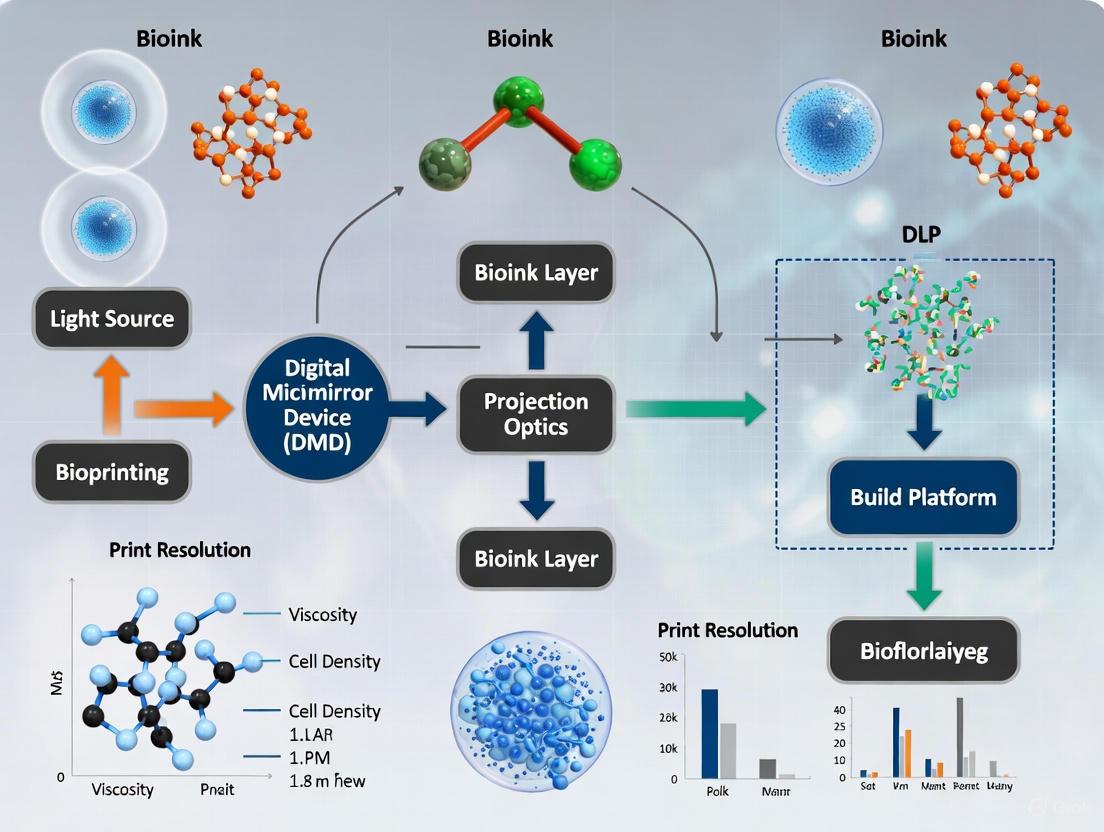
In high-resolution bioprinting, Digital Light Processing (DLP) technology stands out for its ability to fabricate complex structures with micron-scale precision. The core of this technology is the Digital Micromirror Device (DMD), a spatial light modulator that enables the simultaneous curing of entire resin layers through dynamic photomask projection. This layer-wise photopolymerization process offers significant advantages for creating biomimetic tissue scaffolds with intricate architectures essential for advanced tissue engineering and drug development applications [1] [2].
A DMD is a micro-electro-mechanical system (MEMS) consisting of an array of hundreds of thousands to millions of microscopic mirrors, each functioning as an individual pixel [3] [4]. Each micromirror is mounted on a semiconductor chip and can be individually tilted to precise angles (±12-17°) through applied digital voltage signals, allowing digital control of light reflection patterns [1]. In DLP-based bioprinting systems, these devices serve as dynamic masks by projecting UV light patterns onto photopolymerizable bioinks, curing complete cross-sections in a single exposure and thus enabling rapid fabrication of complex 3D structures [5] [1].
Core Operating Principle and Technical Specifications
The Layer-by-Layer Curing Mechanism
The DMD-enabled curing process operates through a precise sequence that builds constructs layer by layer, with the DMD chip providing the optical pattern for each layer through its array of digitally controlled microscopic mirrors [2].
The following diagram illustrates the operational workflow of a DMD-based bioprinting system:
Figure 1: DMD Operational Workflow in Bioprinting. This diagram illustrates how patterned UV light from the DMD chip selectively cures bioink layers on the build platform.
Technical Advantages for Bioprinting Applications
The DMD-based approach offers several critical advantages for biomedical applications:
- High-Speed Fabrication: By curing entire layers simultaneously rather than tracing contours point-by-point, DLP systems achieve significantly faster build times compared to other photopolymerization technologies like laser-based SLA [1] [6].
- Excellent Resolution: DMD chips contain microscale mirrors (as small as 10 microns) that can achieve high-resolution features down to 32 nm with advanced optical systems, enabling fabrication of scaffolds with fine architectural details that mimic native tissue extracellular matrix [1].
- Precision Control: Each micromirror can be rapidly switched (within microseconds) between ON and OFF states, allowing precise control of light exposure and thus polymerization depth and degree [3] [1].
Table 1: Key Technical Specifications of DMD-Based Bioprinting Systems
| Parameter | Typical Range | Impact on Bioprinting |
|---|---|---|
| Mirror Size | 10-20 μm | Determines XY resolution and minimum feature size |
| Switching Speed | Microseconds | Enables rapid patterning and grayscale curing |
| Array Size | Up to 4K resolution (3840×2160) | Defines maximum build area without stitching |
| UV Wavelength | 385 nm [6] | Must match photoinitiator absorption peak |
| Layer Thickness | 10-100 μm | Controls Z-axis resolution and manufacturing time |
Quantitative Performance Data
The performance of DMD-based bioprinting systems is characterized by several key parameters that directly impact their suitability for specific research applications.
Table 2: Performance Comparison of Vat Photopolymerization Technologies
| Performance Metric | DLP (DMD-Based) | SLA | LCD (mSLA) |
|---|---|---|---|
| Print Speed | Fast [6] | Medium/Fast [6] | Very Fast [6] |
| XY Resolution | Excellent (mirror-dependent) [2] | Excellent (laser spot-size dependent) | Medium [6] |
| Z-Axis Resolution | 10-100 μm | 25-100 μm | 25-100 μm |
| Light Source Efficiency | High (reflective) [1] | Medium (galvanometer) | Lower (LCD absorption) [6] |
| Material Versatility | Broad range [6] | Broad range [6] | Limited [6] |
Experimental Protocol: DLP Bioprinting of Cell-Laden Constructs
Research Reagent Solutions
Table 3: Essential Materials for DLP Bioprinting Experiments
| Reagent/Material | Function | Example Formulations |
|---|---|---|
| Photopolymerizable Bioink | Forms hydrogel scaffold upon light exposure; provides cellular microenvironment | Methacrylated collagen (CMA) [7], GelMA [5] [8], PEGDA [5] [8] |
| Photoinitiator | Absorbs UV light and generates free radicals to initiate polymerization | Lithium phenyl-2,4,6-trimethylbenzoylphosphinate (LAP) [5] [7], TPO [5] |
| Biologically Active Additives | Enhance bioactivity, mechanical properties, or provide specific biological functions | Dihydromyricetin (antioxidant) [7], nanoceramics (mechanical reinforcement) [5] |
| Cell Suspension | Provides living component for tissue formation | Primary cells or cell lines specific to target tissue (e.g., human dermal fibroblasts) [7] |
Step-by-Step Bioprinting Protocol
Protocol Title: DLP Bioprinting of Cell-Laden Collagen-Based Constructs for Tissue Engineering Applications
Background: This protocol describes the fabrication of 3D cell-laden scaffolds using a DLP bioprinter with a methacrylated collagen bioink, suitable for creating patient-specific tissue models for drug screening and regenerative medicine [7].
Materials Preparation:
- Bioink Formulation: Prepare a photopolymerizable bioink by combining methacrylated collagen (CMA, 2-5% w/v) with dihydromyricetin (DHM, 0.5-1 mg/mL) as an antioxidant and anti-inflammatory agent [7].
- Photoinitiator Addition: Dissolve LAP photoinitiator (0.1-0.3% w/v) in the bioink solution, ensuring uniform distribution while protecting from light.
- Cell Incorporation: Mix a cell suspension (1-10 million cells/mL) with the bioink immediately before printing, maintaining sterility and cell viability.
Bioprinting Procedure:
- System Setup:
- Initialize the DLP bioprinter and ensure the UV light source (385 nm) is calibrated.
- Sterilize the build platform and resin vat using appropriate methods (e.g., UV irradiation, ethanol treatment).
- Preheat the bioink reservoir to maintain optimal viscosity (if required).
Print Parameters Configuration:
- Set layer thickness to 25-50 μm based on desired resolution and construct height.
- Adjust exposure time (typically 5-30 seconds per layer) based on bioink photosensitivity.
- Configure light intensity to 10-20 mW/cm² at the build surface.
Print Execution:
- Import the 3D model file (STL format) and slice into sequential 2D layers.
- Transfer bioink-cell mixture to the resin vat.
- Initiate the printing sequence:
- The build platform lowers to create a thin bioink layer.
- The DMD projects the first layer pattern, curing the bioink.
- The platform elevates to allow resin flow and the process repeats.
Post-Processing:
- Carefully retrieve the printed construct from the build platform.
- Rinse with sterile PBS to remove uncured bioink.
- Perform secondary crosslinking if required (e.g., additional UV exposure).
- Transfer to cell culture medium and maintain under standard culture conditions.
Troubleshooting Notes:
- Incomplete Curing: Increase exposure time or photoinitiator concentration.
- Poor Cell Viability: Reduce UV exposure time or intensity; incorporate higher concentrations of radical scavengers.
- Layer Delamination: Optimize exposure time to ensure adequate interlayer bonding.
Applications in Biomedical Research
DMD-based DLP bioprinting has enabled significant advances in numerous biomedical research areas:
Tissue Engineering and Regenerative Medicine: Fabrication of complex, patient-specific scaffolds for bone, cartilage, and soft tissues using materials including bioceramics, polymers, and hydrogels [5] [1]. These scaffolds support cell attachment, proliferation, and differentiation while providing appropriate mechanical properties.
Organ-on-a-Chip and Disease Modeling: Creation of microscale tissue constructs with vascular networks for drug screening and disease mechanism studies [8] [9]. The high resolution of DLP enables fabrication of capillary-like structures that support nutrient transport.
Personalized Medical Devices: Production of custom-fit implants, surgical guides, and dental restorations with high precision and accuracy [5] [2]. The technology enables rapid prototyping of patient-specific designs based on medical imaging data.
The following diagram summarizes the experimental workflow integrating these applications:
Figure 2: DLP Bioprinting Experimental Workflow. This diagram outlines the complete process from design to application of DLP-bioprinted constructs.
Digital Micromirror Devices represent a cornerstone technology in high-resolution bioprinting, enabling the simultaneous curing of entire bioink layers through precise spatial light modulation. The core operating principle—utilizing digitally controlled micromirror arrays to project dynamic UV patterns—provides exceptional speed, resolution, and precision for fabricating complex 3D tissue constructs. As DMD technology continues to advance with higher mirror densities and faster switching speeds, and as bioink formulations become increasingly sophisticated, DLP-based bioprinting is poised to enable increasingly complex tissue models for drug development, disease research, and regenerative medicine applications.
Key Characteristics of DLP Bioprinting
Table 1: Quantitative Characteristics of DLP Bioprinting Technology
| Characteristic | Typical Performance Range | Influencing Factors | Comparison to Extrusion Bioprinting |
|---|---|---|---|
| Resolution (X-Y axis) | 25-50 μm [10] | DMD pixel size, optical magnification, bioink scattering properties [10] | Higher resolution [10] |
| Printing Speed | mm³/s scale [10] | Layer thickness, photocrosslinking efficiency [10] | Faster for volumetric structures [10] |
| Surface Finish | High, enabling complex geometries [5] | Light penetration depth, bioink reactivity, pixel optimization [5] | Superior for intricate architectures [11] |
| Cell Viability | High (maintains post-printing viability) [12] | Photoinitiator concentration, exposure time, RI matching [12] | Comparable to laser-assisted methods [11] |
Digital Light Processing (DLP) bioprinting stands out in the field of additive manufacturing for its ability to produce highly precise structures using photopolymerizable materials. This technology enables the production of complex, biomimetic tissue constructs with high resolution and superior surface finish, making it particularly valuable for applications requiring intricate geometries and smooth surfaces [5]. The technology's speed advantage stems from its layer-by-layer projection method rather than linear filament deposition, allowing rapid fabrication of volumetric structures [10].
Experimental Protocols
Protocol: DLP Bioprinting with Composable Gradients Using a Microfluidic Mixer
This protocol details the methodology for generating constructs with continual or discrete gradients of materials, cell densities, and mechanical properties using a microfluidic chaotic mixer-integrated DLP system [10].
Research Reagent Solutions:
- Poly(ethylene glycol) diacrylate (PEGDA) or Gelatin methacryloyl (GelMA)-based bioinks: Serve as photopolymerizable hydrogels for cell encapsulation and scaffold formation [10].
- Iohexol (IHX)-based bioink: Functions as a refractive index tuning agent to mitigate light scattering in high cell density bioprinting, improving resolution and fidelity [12].
- Lithium phenyl-2,4,6-trimethylbenzoylphosphinate (LAP): A biocompatible photoinitiator for visible light crosslinking (450 nm blue light, 0.5 mW cm⁻²) [10].
- Cell suspensions: Primary cells or cell lines relevant to target tissue (e.g., epithelial, endothelial, parenchymal, stem cells) [12].
Equipment Setup:
- DLP Bioprinter: System equipped with Digital Micromirror Device (DMD), 450 nm blue light source (0.5 mW cm⁻²), and build platform [10].
- Microfluidic Mixer Chip: Fabricated with:
- Multiple inlets for different bioinks
- Chaotic mixer microchannel (350 μm height, 1.5 mm width) with slanted ribs (35.6° angle, 100 μm height) to induce helical flow
- (Bio)ink vat (72.96 × 41.04 mm² projection area) [10]
- Computer System: For controlling flow ratios and projecting desired light patterns [10].
Experimental Workflow:
Step-by-Step Procedure:
Bioink Preparation (Day 1)
- Prepare PEGDA or GelMA hydrogels supplemented with 0.1-0.25% (w/v) LAP photoinitiator [10].
- For high cell density printing, incorporate iohexol (IHX) to match refractive index of cellular components (typically 2-5% w/v) [12].
- Mix bioink with cell suspension to achieve desired cell density (typically 1-20 million cells/mL), maintaining temperature control for cell viability [12].
System Calibration (Day 1)
- Prime microfluidic mixer channels with PBS to remove air bubbles.
- Calibrate light intensity to 0.5 mW cm⁻² at the vat surface using a radiometer [10].
- Verify focus and alignment of projected patterns using test structures.
Gradient Bioprinting (Day 1)
- Load different bioink compositions into separate microfluidic inlets.
- Set flow rate ratios to achieve desired gradient profiles (e.g., 30:70, 50:50, 70:30).
- Initiate flow through chaotic mixer, allowing homogeneous mixing via helical flow patterns.
- Fill vat with gradient bioink mixture.
- Lower build platform to printing level (adjust layer thickness based on resolution requirements).
- Project desired light patterns with 1-10 second exposure times per layer, optimizing for bioink reactivity [10].
- Continue layer-by-layer projection until construct completion.
Post-processing (Day 1)
- Carefully retrieve printed construct from build platform.
- Rinse with sterile PBS to remove uncrosslinked bioink.
- Transfer to appropriate cell culture medium and conditions for maturation [12].
Troubleshooting Tips:
- Incomplete curing: Increase exposure time or photoinitiator concentration.
- Poor gradient fidelity: Verify mixer channel geometry and flow rates.
- Low cell viability: Reduce exposure time, optimize RI matching with IHX [12].
- Layer adhesion issues: Adjust exposure time and layer thickness.
Protocol: Refractive Index-Tuned High Cell Density DLP Bioprinting
This protocol specifically addresses the challenge of maintaining high resolution and structural fidelity when printing at high cell densities, utilizing iohexol as an RI-tuning agent [12].
Research Reagent Solutions:
- Iohexol (IHX): Non-ionic, iodinated contrast agent used at 2-5% (w/v) for RI matching [12].
- LAP photoinitiator: Cytocompatible photoinitiator at 0.1-0.25% (w/v) for visible light crosslinking [12].
- Base hydrogel: PEGDA (MW 200-700 Da) or GelMA (5-10% w/v) [12].
- Cell culture medium: Appropriate for specific cell type used.
Procedure:
- IHX-Bioink Formulation
- Dissolve IHX in base hydrogel solution to achieve final concentration of 2-5% (w/v).
- Add LAP photoinitiator at 0.1-0.25% (w/v) and mix thoroughly.
- Sterilize solution by filtration (0.22 μm pore size).
- Mix with cell suspension to achieve high cell density (10-50 million cells/mL) [12].
DLP Printing Parameters
- Set layer thickness to 25-50 μm based on desired resolution.
- Adjust exposure time (typically 5-15 seconds) based on bioink formulation.
- Project patterns for tubular constructs with lumen diameters of 400 μm to 1.1 mm [12].
Post-printing Analysis
- Assess cell viability via live/dead staining (typically >85% viability expected).
- Evaluate lumen fidelity and structural integrity through histology and microscopy.
- Test functionality through perfusion assays for vascular constructs [12].
Applications and Biomimetic Potential
Table 2: DLP Bioprinting Applications in Tissue Engineering
| Application Field | Recommended Materials | Key Achievements | Reference |
|---|---|---|---|
| Bone Tissue Engineering | Bioceramics (hydroxyapatite, β-TCP), polymer-based materials | Scaffolds with high mechanical strength, osteoinductive implants | [5] |
| Soft Tissue Engineering | GelMA, PEGDA, elastomeric polymers | Elastic vascular grafts, vessel-like structures, cartilage repair | [5] |
| Vascularized Constructs | PEGDA, GelMA with IHX-tuning | Tubular constructs with lumens (400 μm-1.1 mm), perfusable networks | [12] |
| Multi-layered Tissue Models | Polymer blends, nanocomposites | Endothelial-epithelial interfaces, tissue heterogeneity | [13] |
| Drug Screening & Disease Modeling | Cell-laden hydrogels, stimuli-responsive materials | Tumor microenvironment models, organ-specific microenvironments | [14] |
DLP bioprinting enables the fabrication of constructs with spatially controlled biomimetic properties. The integration of composable gradients allows replication of native tissue interfaces, such as osteochondral junctions or vascular density variations [10]. The technology's high resolution supports creation of microarchitectural features essential for proper tissue function, including pore networks for nutrient diffusion and vascular channels for perfusion [5] [12].
The future of DLP bioprinting lies in advancing multi-material capabilities, integrating artificial intelligence for optimized printing parameters, and developing novel stimuli-responsive bioinks for 4D bioprinting applications [11]. These developments will further enhance the technology's potential for creating clinically relevant tissue constructs for regenerative medicine and drug development.
Digital Light Processing (DLP) bioprinting has emerged as a groundbreaking method in biomedical engineering, enabling the production of highly precise, complex structures from photopolymerizable materials for tissue engineering and regenerative medicine [15] [5]. This technology stands apart from other bioprinting methods, particularly extrusion bioprinting, through its distinctive mechanism of using projected light patterns to cure entire layers of photopolymerizable materials simultaneously [16]. While extrusion bioprinting excels in multi-material printing, DLP offers superior resolution, smoother surface finishes, and enhanced capability for creating intricate geometries and water-tight structures essential for microfluidic applications and vascular networks [16]. The success of DLP bioprinting hinges on the development of advanced biomaterials—including smart materials, hydrogels, and biocompatible resins—that not only facilitate high-fidelity printing but also support biological function [15]. This application note provides a detailed overview of the current biomaterial toolkit for DLP bioprinting, complete with quantitative data comparisons and standardized experimental protocols to accelerate research in this rapidly advancing field.
The Biomaterial Landscape: Materials for DLP Bioprinting
The expanding repertoire of biomaterials compatible with DLP technology enables researchers to tailor scaffolds for specific tissue engineering applications, from bone regeneration to soft tissue reconstruction.
Material Classes and Key Applications
Table 1: Biomaterial Classes for DLP Bioprinting and Their Applications
| Material Class | Specific Examples | Primary Applications | Key Characteristics |
|---|---|---|---|
| Smart Materials | Shape memory polymers, Temperature/pH-responsive hydrogels [15] | Drug delivery systems, Actuators, Dynamic tissue scaffolds [15] | Sensitivity to environmental stimuli (temperature, pH, humidity) [15] |
| Hydrogels | GelMA, HAMA, PEGDA, Silk-MA, Collagen-riboflavin, PAAm-Alginate [15] [17] [18] | Soft tissue engineering, Cartilage repair, Vascular grafts, Cultivated meat [15] [17] | High water content, Biocompatibility, Tunable mechanical properties [18] |
| Bioceramics | Hydroxyapatite (HA), β-Tricalcium phosphate (β-TCP), Bioglass [15] | Bone tissue engineering, Dental implants, Hard tissue regeneration [15] | High mechanical strength, Osteoconductivity, Biocompatibility [15] |
| Polymer-Based Materials | Poly L-lactic acid (PLLA), Trimethylolpropane trimethacrylate (TMPTMA) [15] | Bone tissue engineering, Regenerative medicine, Biodegradable implants [15] | Biodegradability, High mechanical strength, Customizable properties [15] |
| Nanocomposites | Polyurethane acrylate with ZnO nanoparticles, Barium titanate/hydroxyapatite [15] | Targeted drug delivery, Biosensors, Tissue engineering [15] | Enhanced mechanical/biological properties, Multi-functionality [15] |
| Cellulose Derivatives | Methacrylated carboxymethyl cellulose (M-CMC), Allyl cellulose [19] [20] | Biomedical hydrogels, Tissue scaffolds [20] | Bio-based source, Biocompatibility, FDA-approved derivative [20] |
Quantitative Comparison of DLP-Printed Hydrogels
Table 2: Mechanical and Biological Properties of Representative DLP-Hydrogel Formulations
| Hydrogel Formulation | Compressive Modulus | Maximum Compressive Stress | Biological Performance | Key Application Evidence |
|---|---|---|---|---|
| Collagen-riboflavin (8 mg/mL collagen, 0.1% riboflavin) [17] | 1933 ± 175 Pa [17] | 243 ± 24 kPa [17] | Significant increase in live cell density (860 to 2647 cells/mm²) over 4 days [17] | Cultivated meat production [17] |
| PAAm-Alginate (with Fe³⁺ post-processing) [18] | Adjustable 15.8–345 kPa [18] | Not specified | Effective support for cardiac tissue growth and vascular scaffold formation [18] | Broad-range tissue-mimicking scaffolds [18] |
| Methacrylated CMC (20 mg/mL in water) [20] | Storage modulus (G'): ~10 kPa (after UV curing) [20] | Not specified | Good fibroblast (NIH/3T3) viability and proliferation [20] | Biocompatible hydrogels for tissue engineering [20] |
| PEGDA Hydrogel [15] | Varies with molecular weight and concentration | Not specified | Supports cell expansion and regeneration [15] | Arthroscopic cartilage repair, minimally invasive surgical platforms [15] |
Diagram 1: A decision workflow for selecting biomaterials in DLP bioprinting based on target tissue application and required material properties.
Experimental Protocols: Standardized Methods for DLP Biomaterial Processing
Protocol 1: DLP Bioprinting of Collagen-Riboflavin Hydrogels for Tissue Engineering
This protocol details the methodology for creating cell-supportive collagen-based constructs using DLP, suitable for applications such as cultivated meat production and soft tissue engineering [17].
Research Reagent Solutions:
- Type I Collagen Solution (8 mg/mL in acidic suspension)
- Riboflavin Stock Solution (0.5% in DI water)
- Cell Culture Medium (DMEM/F12 with appropriate supplements)
- Phosphate Buffered Saline (PBS) (1×, sterile)
- Photoinitiator (if additional to riboflavin is required)
Procedure:
- Bioink Preparation:
- Neutralize the type I collagen solution using sterile NaOH or culture medium to achieve physiological pH (7.2-7.4).
- Add riboflavin stock solution to the neutralized collagen to achieve a final concentration of 0.1% riboflavin.
- Gently mix the solution to ensure homogeneity without introducing air bubbles.
- For cell-laden constructs, resuspend cells in the collagen-riboflavin bioink at the desired density (e.g., 5-10 million cells/mL).
DLP Printing Parameters:
- Load the bioink into the printing reservoir of the DLP bioprinter.
- Set the printing parameters as follows:
- Layer thickness: 50-100 μm
- Exposure time: 4-6 seconds per layer
- Light intensity: 5-15 mW/cm² at 405 nm
- Initiate the printing process based on the sliced CAD model of the desired scaffold.
Post-Printing Processing:
- Gently rinse the printed constructs in sterile PBS to remove uncured material.
- Transfer constructs to cell culture medium and maintain at 37°C, 5% CO₂.
- Change culture medium every 2-3 days for long-term cultures.
Quality Control Measures:
- Perform rheological characterization to confirm storage modulus (G') > loss modulus (G'') after crosslinking.
- Validate mechanical properties through compressive testing; expected modulus ~1900 Pa for collagen-riboflavin constructs.
- Assess cell viability using live/dead staining at 24, 48, and 72 hours post-printing.
Protocol 2: Two-Step Hydrogel Modulus Adjustment via Post-Printing Ionic Crosslinking
This innovative protocol enables broad modulation of hydrogel mechanical properties after DLP printing using a single initial formulation, allowing customized mechanical environments for different tissue types [18].
Research Reagent Solutions:
- UV-Curable Hydrogel Solution (PAAm-Alginate: AAm:PEGDA:LAP:Tartrazine:DI water = 1:0.03:0.03:0.015:4)
- Ethanol Solution (40 wt% in DI water)
- FeCl₃·6H₂O Solutions (varying concentrations from 0.005 M to 1 M in DI water)
- Deionized Water
Procedure:
- Hydrogel Fabrication via DLP:
- Prepare the UV-curable hydrogel solution with desired alginate content (1-6% Alg/AAm ratios).
- Fabricate samples using a DLP printer (e.g., BMF Precision S240) with the following parameters:
- Resolution: 10 μm
- Light energy density: 43.1 mW/cm² at 405 nm
- Layer thickness: 10-40 μm
- Exposure time: 4-6 seconds per layer
Post-Printing Processing:
- Immerse printed samples in 40 wt% ethanol solution for 15 minutes to dissolve uncured surface material.
- Dry sample surfaces using a high-pressure air gun.
- Post-cure under UV light (1000 mW) for 15 minutes.
Ionic Crosslinking for Modulus Tuning:
- Prepare Fe³⁺ solutions at varying concentrations (0.005 M, 0.01 M, 0.02 M, 1 M) based on desired final modulus.
- Soak samples in the selected Fe³⁺ solution for 24 hours to ensure complete ion exchange and crosslinking.
- Use a sufficient volume of Fe³⁺ solution to maintain stable ion concentration during soaking.
- Transfer samples to DI water for 7 days to allow uniform diffusion of Fe³⁺ throughout the hydrogel.
Characterization and Validation:
- Perform mechanical testing using universal testing machine @ 2 mm/min with 50 N load cell.
- Confirm modulus adjustment range of 15.8-345 kPa, covering various tissue mechanical environments.
- Conduct swelling behavior evaluation using rectangular specimens (16 mm × 10 mm × 2 mm) over 7 days.
- Validate biocompatibility through CCK-8 assays with fibroblast cells cultured in hydrogel extracts.
Diagram 2: Standard experimental workflow for DLP bioprinting of biomaterials, from design to biological validation.
The Scientist's Toolkit: Essential Research Reagent Solutions
Table 3: Key Research Reagent Solutions for DLP Biomaterial Research
| Reagent Category | Specific Examples | Function | Application Notes |
|---|---|---|---|
| Photoinitiators | LAP (Lithium phenyl-2,4,6-trimethylbenzoylphosphinate), TPO [15] [18] [20] | Initiate photopolymerization upon light exposure | LAP offers biocompatibility and efficient curing at 405 nm; concentration typically 0.5-3 wt% [18] [20] |
| UV Absorbers | Tartrazine, Other light-absorbing dyes [18] | Control penetration depth of curing light, improve resolution | Concentration optimization critical for balancing resolution and curing depth [18] |
| Monomers/ Macromers | PEGDA, AA (Acrylamide), HEMA, Functionalized polymers (GelMA, M-CMC) [15] [18] [20] | Form primary polymer network upon crosslinking | Molecular weight and functional group density dictate mechanical properties [20] |
| Crosslinkers | PEGDA (for covalent), Fe³⁺ ions (for ionic) [18] | Enable network formation through covalent or ionic bonds | Dual crosslinking systems enable enhanced mechanical properties [18] |
| Bioceramic Fillers | Hydroxyapatite nanoparticles (100-200 nm), β-TCP [15] | Enhance mechanical strength, provide bioactivity | Particle size and distribution critical for resin stability and curing [15] |
| Cell Support Additives | DMEM, Growth factors, Adhesion peptides [20] | Maintain cell viability and function during and after printing | Osmolarity and pH adjustment necessary for cell-laden bioinks [20] |
The biomaterial toolkit for DLP bioprinting has expanded significantly to include diverse classes of smart materials, hydrogels, and biocompatible resins that enable high-precision fabrication of tissue-engineered constructs. The standardized protocols and quantitative data presented in this application note provide researchers with practical methodologies for implementing these advanced materials in their DLP bioprinting workflows. Future developments in this field will likely focus on expanding material diversity, improving multi-material printing capabilities, and enhancing the biological functionality of printed constructs [15] [16]. The integration of artificial intelligence and machine learning approaches for optimizing biomaterial properties and printing parameters represents a promising frontier for advancing DLP bioprinting capabilities [15]. As these biomaterials and protocols continue to evolve, they will further accelerate the translation of DLP-bioprinted constructs toward clinical applications in regenerative medicine, drug development, and personalized medicine.
In digital light processing (DLP) bioprinting, the successful fabrication of high-resolution, functional tissue constructs hinges on two fundamental resin properties: photosensitivity and light penetration [5] [21]. Photosensitivity dictates the efficiency with which a resin undergoes polymerization upon light exposure, while light penetration determines the depth and uniformity of curing, directly impacting the structural integrity and dimensional accuracy of printed constructs [22] [23]. Mastering the interplay of these properties is essential for advancing DLP applications in regenerative medicine, tissue engineering, and drug development [5].
The move towards bio-based resins, such as acrylated epoxidized soybean oil (AESO) and functionalized gelatin, represents a significant innovation, offering enhanced biocompatibility and reduced environmental impact [24]. Furthermore, the adoption of advanced photochemical mechanisms, like thiol–ene step-growth reactions, provides superior reaction kinetics and network homogeneity compared to traditional chain-growth polymerizations, enabling the fabrication of complex structures with high cell viability [25]. This application note details the characterization and application of these advanced resins within a DLP bioprinting framework.
Core Principles and Key Parameters
The Photopolymerization Process
In DLP bioprinting, photopolymerization is a light-mediated process where photons are absorbed by a photoinitiator (PI), generating reactive species that initiate the cross-linking of monomeric and oligomeric resins into a solid polymer network [23]. The Beer-Lambert law provides the foundational relationship describing light attenuation through a photoresin:
[ \textbf{I(z) = I₀e^{-\alpha z}} ]
Here, I(z) is the irradiance at depth z, I₀ is the incident irradiance at the surface, and α is the absorption coefficient of the resin, which is heavily influenced by the concentration and molar absorptivity of the PI, as well as the presence of pigments and fillers [22] [23].
Quantitative Parameters for Resin Characterization
The following parameters are critical for quantifying and controlling the photopolymerization process in DLP bioprinting.
Table 1: Key Quantitative Parameters in DLP Bioprinting
| Parameter | Symbol | Units | Definition | Impact on Bioprinting |
|---|---|---|---|---|
| Radiant Exposure | E | J/cm² | Total light energy delivered per unit area: E = I × t (Irradiance × Time) [23]. | Determines the degree of monomer conversion; insufficient exposure causes under-curing [26]. |
| Penetration Depth | Dₚ | µm or mm | Depth where irradiance drops to 1/e (≈37%) of surface value; Dₚ = 1/α [25] [24]. | Governs maximum achievable layer thickness and vertical resolution [21]. |
| Critical Energy | Eᶜ | mJ/cm² | Minimum radiant exposure required to initiate gelation at the resin surface [25]. | Defines the polymerization threshold and minimum exposure for printing. |
| Gelation Time | t_gel | seconds | Time at which storage modulus (G') surpasses loss modulus (G") during photorheometry [24]. | Indicates resin reactivity and required per-layer exposure time. |
Table 2: Measured Penetration Depth and Gelation of Representative Resins
| Resin Formulation | Photoinitiator | Wavelength | Penetration Depth (Dₚ) | Gelation Time (t_gel) | Source |
|---|---|---|---|---|---|
| Gelatin-Norbornene | LAP | 405 nm | ~250 µm | ≈10-11 s (for volumetric printing) [25] | [25] |
| AESO | None (Pure) | 385 nm | ~2.0 mm | Not achieved [24] | [24] |
| AESO | BAPO (1% w/w) | 385 nm | ~250 µm | ~5 s [24] | [24] |
| AESO | TPO (1% w/w) | 385 nm | ~300 µm | ~10 s [24] | [24] |
| PEG-DA | TPO | 405 nm | Not explicitly stated | Fast (enables volumetric printing) [25] | [25] |
The data in Table 2 demonstrates how PI selection critically tunes resin performance. For instance, the extremely fast gelation of Gelatin-Norbornene with LAP initiator enables volumetric bioprinting of centimeter-scale constructs in seconds [25].
Figure 1: The Photopolymerization Pathway. This diagram illustrates the fundamental sequence from light absorption to network formation, highlighting key factors that influence photosensitivity and light penetration.
Experimental Protocols for Characterization
Protocol: Measuring Penetration Depth (Dₚ) and Critical Energy (Eᶜ)
This protocol outlines the "Working Curve" method, a standard technique for characterizing resin curing performance [25].
1. Principle: The depth of cure (C_d) for a single exposure is a function of the penetration depth (Dₚ) and the natural logarithm of the exposure energy (E) at the surface, following the working curve equation: C_d = Dₚ ln(E / Eᶜ).
2. Materials & Equipment:
- Photopolymerizable resin
- DLP printer or equivalent light engine with a calibrated UV/blue light source (e.g., 405 nm)
- Digital calipers or profilometer
- Glass slides or vat bottom substitute
3. Procedure:
- A. Sample Preparation: Program the light engine to project a solid rectangle pattern onto the resin vat. Vary the exposure time (t) across a series of exposures while keeping the irradiance (I) constant. This yields a range of surface radiant exposures (E = I × t).
- B. Curing and Measurement: For each exposure, initiate curing. After exposure, carefully remove the resulting cured film. Gently clean any uncured resin from the film.
- C. Data Collection: Measure the thickness of each cured film (C_d) using digital calipers or a profilometer for higher accuracy. Record the corresponding exposure energy E.
4. Data Analysis:
- Plot the measured cure depth (C_d) against the natural logarithm of the exposure energy (ln(E)).
- Perform a linear regression on the data. The slope of the resulting line is the penetration depth, Dₚ. The x-intercept (where C_d = 0) gives ln(Eᶜ), from which the critical energy Eᶜ can be calculated.
Protocol: Real-Time Photorheometry for Gelation Time
This protocol uses photorheometry to monitor the in-situ evolution of mechanical properties during curing [24].
1. Principle: A rheometer with a transparent plate applies oscillatory stress to a resin sample while simultaneously exposing it to UV/blue light. The instrument measures the evolution of the storage modulus (G') and loss modulus (G"), identifying the gel point (t_gel) when G' surpasses G".
2. Materials & Equipment:
- Photorheometer equipped with a UV/blue light source (wavelength matched to the resin's PI)
- Resin sample
3. Procedure:
- A. Instrument Setup: Load the resin sample between the rheometer plates, ensuring a consistent gap. Configure the light source to deliver a specific, constant irradiance.
- B. Simultaneous Testing: Initiate both the oscillatory measurement and the light exposure simultaneously. Track G' and G" in real-time throughout the exposure.
4. Data Analysis:
- Identify the gel point as the time t_gel where the G' and G" curves intersect (G' = G").
- The subsequent rate of increase of G' indicates the kinetics of network formation and the final stiffness that can be achieved.
The Scientist's Toolkit: Research Reagent Solutions
Table 3: Essential Materials for DLP Bioprinting Research
| Reagent / Material | Function / Description | Example Formulations |
|---|---|---|
| Photoinitiators (PIs) | Absorb light and generate radicals to initiate polymerization. Choice depends on wavelength and biocompatibility. | LAP (Lithium phenyl-2,4,6-trimethylbenzoylphosphinate): Biocompatible, used for cell-laden gels [25]. BAPO & TPO: High reactivity for synthetic and bio-based resins [24]. |
| Base Polymers & Resins | Form the primary matrix of the printed structure. | Gelatin-Norbornene (Gel-NB): Crosslinks via fast, biocompatible thiol–ene chemistry [25]. AESO (Acrylated Epoxidized Soybean Oil): Bio-derived, suitable for multi-scale printing [24]. PEG-DA (Poly(Ethylene Glycol) Diacrylate): Hydrogel used for soft tissue engineering [5]. |
| Crosslinkers / Co-monomers | Modulate network structure and mechanical properties. | Dithiol Crosslinkers: React with norbornene groups in Gel-NB in a step-growth mechanism [25]. |
| Biocompatible Fillers | Enhance mechanical properties and introduce bioactivity. | Bioceramics (Hydroxyapatite, β-TCP): For bone tissue engineering scaffolds [5] [27]. Natural Fillers (Cotton, Eggshell): Can improve tensile properties of composite resins [27]. |
| Absorbers / Dyes | Control light penetration depth to improve resolution. | UV Blockers (e.g., OB+): Added in precise concentrations to confine curing to a defined layer thickness [28]. |
Advanced Resin Systems and Formulation Strategies
Thiol–Ene Step-Growth Resins
Traditional chain-growth polymerizations (e.g., of Gelatin-Methacryloyl, Gel-MA) can lead to heterogeneous networks and significant shrinkage. Thiol–ene step-growth polymerizations, as exemplified by Gelatin-Norbornene (Gel-NB) crosslinked with a dithiol, offer superior alternatives [25]. These systems provide:
- Homogeneous Networks: Reduced polymerization stress and shrinkage.
- Rapid Kinetics: Enable volumetric bioprinting of complex structures in 10–20 seconds.
- High Cell Viability: Require lower radical concentrations and polymer content, creating a more permissive environment for encapsulated cells [25].
Strategies for Opaque and Filled Composites
A significant challenge in DLP is printing with resins containing opaque fillers like metals or dense bioceramics, which scatter and absorb light, preventing deep curing [22]. Advanced strategies to overcome this include:
- Photothermal Synergistic Curing: Utilizing exothermic heat from superficial photopolymerization to drive thermal initiation deeper within the opaque resin, enabling the fabrication of iron-polymer composites with 50% filler content [22].
- Optimized PI Systems: Employing photoinitiators like Irgacure 369 in combination with charge-transfer complexes that act as dual thermal/photochemical initiators [22].
Figure 2: Resin Formulation Selection Workflow. A decision-making guide for selecting and optimizing resin chemistry based on the primary objective of the bioprinting application, balancing biocompatibility, speed, and material properties.
From Bench to Bedside: DLP Applications in Tissue Engineering and Pharmaceutical Development
Application Notes
Digital Light Processing (DLP) bioprinting is a vat photopolymerization technology that uses projected light to cure photopolymerizable bioinks layer-by-layer, achieving high resolution and efficiency for fabricating complex tissue constructs [15] [29]. This technology is particularly suited for engineering tissues with intricate anatomical shapes, such as bone, cartilage, and vascular networks, by processing smart biomaterials including shape memory polymers, hydrogels, and nanocomposites [15].
Technical Performance of DLP in Tissue Engineering
Table 1: Performance Comparison of Bioprinting Technologies for Tissue Engineering
| Bioprinting Technology | Printing Efficiency (mm³/s) | Minimum Resolution | Typical Cell Viability | Key Tissue Applications |
|---|---|---|---|---|
| DLP Bioprinting [29] | 0.648 – 840 | ~2 μm [29] | Varies with bioink [29] | Bone scaffolds, Cartilage patches, Acellular vascular constructs |
| Extrusion Bioprinting [29] | 0.00785 – 62.83 | ~100 μm | 40% – 90% | High-cell-density tissues, Vascularized constructs |
| Inkjet Bioprinting [29] | 1.67×10⁻⁷ – 0.036 | ~10 μm | 74% – 85% | Cell patterning, Thin tissue layers |
Key Applications and Outcomes
- Bone Tissue Engineering: DLP enables fabrication of scaffolds from bioceramics like hydroxyapatite (HA) and β-tricalcium phosphate (β-TCP), which mimic the mineral composition of native bone [15]. These scaffolds support osteoblast maturation and bone regeneration, with compressive mechanical properties tunable to match trabecular bone [15].
- Cartilage Tissue Engineering: Photocrosslinkable hydrogels like GelMA and PEGDA are used in DLP to create scaffolds that support chondrocyte expansion and cartilage-specific ECM production [15]. Applications include arthroscopic cartilage repair and self-assembling microscaffolds [15].
- Vascular Network Engineering: While direct DLP bioprinting of perfusable, cell-laden microvessels remains challenging, the technology creates acellular vascular guides with high resolution [30]. Strategies like sacrificial printing combined with DLP-fabricated outer structures help create hierarchical vascular networks [30].
Experimental Protocols
Protocol 1: DLP Bioprinting of Collagen-Based Constructs for Soft Tissue Engineering
This protocol adapts a collagen-riboflavin bioink for cultivated meat applications [17] for general soft tissue engineering, including cartilage and vascularized soft tissues.
Research Reagent Solutions
Table 2: Essential Reagents for Collagen-Based DLP Bioprinting
| Reagent | Function/Description |
|---|---|
| Type I Collagen (8 mg/mL) | Primary bioink component, provides natural ECM microenvironment for cell adhesion and growth [17]. |
| Riboflavin (0.1%) | Photoinitiator; absorbs light to generate radicals that crosslink collagen fibers [17]. |
| Fibroblasts/Chondrocytes | Model cells for assessing construct biocompatibility and tissue formation. |
| Cell Culture Medium | Provides nutrients for cell viability and proliferation post-printing. |
Step-by-Step Procedure
- Bioink Preparation: Prepare a sterile solution of 8 mg/mL type I collagen in a weak acid (e.g., acetic acid) to maintain solubility. Under low-light conditions, add riboflavin to a final concentration of 0.1% (w/v) and mix gently. Keep the bioink on ice until printing to prevent premature gelation [17].
- Cell Encapsulation: For cell-laden constructs, trypsinize and centrifuge the desired cells (e.g., fibroblasts or chondrocytes). Resuspend the cell pellet in the cold collagen-riboflavin bioink to a target density (e.g., 5-10 million cells/mL). Maintain the cell-bioink mixture on ice and use within 30 minutes to maintain cell viability.
- DLP Printer Setup: Load the bioink into the printing vat. Set the printing parameters based on a pre-validated design. Key parameters include: Light Intensity: 5-20 mW/cm²; Layer Exposure Time: 10-30 seconds (optimize for bioink thickness and desired mechanical properties); Layer Thickness: 25-50 μm [15] [17].
- Printing Process: Initiate the printing sequence. The DLP projector will display a sequence of slice images, each curing a single layer of the bioink. After each layer is cured, the build platform will move to allow fresh bioink to flow for the next layer.
- Post-Printing Curing and Washing: Once printing is complete, gently rinse the construct in sterile phosphate-buffered saline (PBS) to remove any uncrosslinked bioink and residual photoinitiator.
- Cell Culture and Maturation: Transfer the bioprinted construct into cell culture medium and incubate under standard conditions (37°C, 5% CO₂). Change the medium every 2-3 days. Culture for up to 14 days to assess cell proliferation and tissue maturation.
Protocol 2: DLP Bioprinting of Bioceramic Scaffolds for Bone Engineering
This protocol outlines the fabrication of high-strength, osteoconductive bone scaffolds using ceramic-polymer composite resins.
Research Reagent Solutions
Table 3: Essential Reagents for Bioceramic DLP Bioprinting
| Reagent | Function/Description |
|---|---|
| Hydroxyapatite (HA) Nanoparticles | Primary ceramic phase; provides osteoconductivity and enhances compressive strength [15]. |
| UV-curable Polymer Resin (e.g., PEGDA, HDDA) | Photopolymerizable matrix that binds ceramic particles and defines the green body structure [15]. |
| Photoinitiator (e.g., TPO, LAP) | Absorbs UV light to initiate the polymerization reaction of the resin [15]. |
| Dispersing Agents | Prevents nanoparticle aggregation for a homogeneous slurry and high-resolution printing. |
Step-by-Step Procedure
- Ceramic Slurry Preparation: Mix hydroxyapatite (HA) nanoparticles (100-200 nm particle size) with a UV-curable polymer resin (e.g., PEGDA or HDDA) at a ceramic loading of 40-60% (w/w). Include 1-2% (w/w) photoinitiator (e.g., TPO) and appropriate dispersing agents. Use a planetary centrifugal mixer to achieve a homogeneous, air-bubble-free slurry with high ceramic loading [15].
- Printer Setup and Parameters: Load the ceramic slurry into the DLP printer vat. Use a slicing software to generate the layer images from the 3D CAD model of the bone scaffold. Optimized printing parameters may include: Layer Thickness: 25-50 μm; Exposure Time per Layer: 20-60 seconds (longer than polymer-only bioinks due to light scattering by ceramics) [15].
- Printing and Post-Processing (Debinding and Sintering): Print the scaffold layer-by-layer. The printed "green" part must undergo post-processing to achieve final mechanical strength. Carefully clean the printed part in a solvent to remove excess resin. Then, subject the construct to a thermal cycle: Debinding: Heat to ~500°C to burn out the polymer matrix; Sintering: Heat to >1100°C to fuse the HA particles into a dense, strong ceramic scaffold [15].
- Sterilization and Seeding: Sterilize the sintered scaffold using autoclaving or gamma irradiation. For in vitro studies, seed the scaffold with osteoprogenitor cells (e.g., BMSCs) by pipetting a concentrated cell suspension onto the structure and allowing for cell attachment before dynamic culture.
Protocol 3: Ultrasonic Patterning Integrated with Bioprinting for Anisotropic Constructs
This protocol describes integrating an Ultrasonic Patterning Fixture (UPF) with a bioprinting system to create aligned cellular architectures within bulk hydrogels, mimicking the anisotropic nature of tissues like muscle, ligament, and vascular bundles [31].
Step-by-Step Procedure
- Setup Integration: Mount the UPF, consisting of an electroacoustic transducer and a rigid reflector, onto or adjacent to the bioprinter's build platform [31].
- Bioink Deposition: Deposit a layer of cell-laden, chemically- or photo-crosslinkable bioink (e.g., alginate, GelMA) into the UPF [31].
- Ultrasonic Patterning: Activate the transducer to generate Standing Bulk Acoustic Waves (SBAW) at a specific frequency (e.g., ~1 MHz). This organizes cells into parallel strands along the pressure nodes within the bioink. Maintain exposure for 10-60 seconds to allow for pattern formation [31].
- Gelation: Crosslink the bioink to lock the cellular pattern in place. For chemical crosslinkers like alginate, add the crosslinking agent (e.g., CaCl₂). For photocurable bioinks like GelMA, expose the layer to light [31].
- Layer-by-Layer Fabrication: Repeat steps 2-4 for subsequent layers. The ultrasound frequency can be modulated between layers to create complex, multi-directional alignment patterns (e.g., 0-45-90°) [31].
- Post-Printing Culture: Transfer the patterned construct to a culture medium and maintain under standard conditions to allow for tissue maturation and ECM remodeling along the patterned directions.
Workflow and Pathway Visualizations
Diagram 1: DLP Bioprinting Workflow for Complex Tissues. This flowchart outlines the integrated experimental pipeline from material preparation to functional assessment, highlighting key stages including ultrasonic patterning for anisotropy and specialized post-processing for different tissue types.
Digital Light Processing (DLP) bioprinting has emerged as a transformative technology in the field of drug discovery, enabling the fabrication of highly precise, biomimetic 3D tissue constructs that closely replicate human physiology. This advanced bioprinting modality utilizes a digital micro-mirror device (DMD) to project patterned light onto photosensitive bioinks, initiating localized photopolymerization and creating complex tissue architectures layer by layer [32]. Unlike conventional drug screening methods that rely on oversimplified 2D cell cultures or species-divergent animal models, DLP-bioprinted tissues offer unprecedented opportunities for developing human-relevant disease models that can better predict clinical efficacy and toxicity [33] [34].
The exceptional resolution of DLP bioprinting, capable of producing features as small as 10 μm, allows for the recreation of critical tissue microfeatures including vascular networks, tissue-specific parenchymal arrangements, and compartmentalized tissue interfaces that are essential for authentic disease modeling [32] [16]. Furthermore, the technology's capacity for high-throughput fabrication aligns with pharmaceutical industry needs for rapid, reproducible assay development during preclinical drug screening phases [35]. This application note provides detailed methodologies and protocols for leveraging DLP bioprinting technology to construct high-fidelity 3D disease models specifically tailored for drug discovery applications.
Operational Principles and Key Advantages
DLP bioprinting operates on the principle of vat photopolymerization, where a digital light projector illuminates entire layers of photosensitive bioresin simultaneously through patterned irradiation [32]. The core components of a DLP bioprinting system include: (1) a digital light projector (DMD or LCD-based), (2) a vat containing photocurable bioink, (3) a motorized build platform, and (4) a computer-controlled system for coordinating layer-by-layer fabrication [36]. The spatial resolution of printed constructs is primarily determined by the pixel size of the projected light, which can be demagnified through optical systems to achieve microscopic features [32].
Key advantages of DLP bioprinting for drug screening applications include:
- High Resolution: Capable of achieving feature sizes between 10-50 μm, enabling reproduction of capillary-scale structures and tissue microarchitectures [32] [16]
- Rapid Fabrication: Entire layers are cured simultaneously, significantly reducing printing time compared to point-by-point deposition techniques [36]
- Excellent Structural Integrity: Continuous layer curing creates monolithic constructs without artificial interfaces between deposition lines [16]
- Geometric Complexity: Enables fabrication of intricate 3D lattice structures and microfluidic networks that mimic native tissue porosity and vascularization [32] [16]
Comparative Analysis of Bioprinting Technologies
Table 1: Comparison of Bioprinting Technologies for Drug Screening Applications
| Parameter | DLP Bioprinting | Extrusion Bioprinting | Inkjet Bioprinting |
|---|---|---|---|
| Resolution | 10-50 μm [32] [16] | 100-1000 μm [33] [16] | 20-50 μm [33] |
| Speed | High (volumetric curing) [36] | Low (point-by-point) [33] | Medium (droplet-by-droplet) [33] |
| Cell Viability | High (>90%) with optimized photoinitiators [32] | Medium-High (80-95%) [33] | High (>90%) [33] |
| Structural Complexity | Excellent for microscale features [32] [16] | Limited for overhanging structures [16] | Limited to simple geometries [33] |
| Multi-material Capability | Limited (requires washing steps) [16] | Excellent (multiple printheads) [16] | Good (multiple reservoirs) [33] |
| Microfluidic Compatibility | Excellent (water-tight structures) [16] | Limited (potential for leakage) [16] | Limited (discontinuous structures) [33] |
Essential Research Reagents and Materials
The successful implementation of DLP bioprinting for disease modeling requires careful selection of bioink components that provide appropriate biochemical, structural, and mechanical cues while maintaining cytocompatibility throughout the printing process.
Table 2: Essential Research Reagents for DLP Bioprinting
| Reagent Category | Specific Examples | Function | Application Notes |
|---|---|---|---|
| Photopolymerizable Hydrogels | GelMA, PEGDA, HAMA, PEG-based hydrogels [15] [34] | Provide 3D scaffold for cell encapsulation and tissue formation | Select based on tissue-specific stiffness and degradation kinetics |
| Photoinitiators | LAP, Irgacure 2959, VA-086 [32] | Initiate photopolymerization upon light exposure | LAP preferred for cell compatibility and visible light activation [32] |
| Photoabsorbers | Ponceau 4R, Tartrazine [32] | Control light penetration depth and improve resolution | Optimize concentration to prevent over-curing while maintaining structural integrity |
| Cell Adhesion Ligands | RGD peptides, laminin, fibronectin [34] | Promote cell-matrix interactions and tissue maturation | Incorporate during bioink formulation or post-printing functionalization |
| Proteolytically Degradable Crosslinkers | MMP-sensitive peptides [34] | Enable cell-mediated remodeling and invasion | Essential for models requiring cell migration and tissue reorganization |
| Support Materials | Carbopol, Pluronic F127 [16] | Facilitate printing of complex overhanging structures | Select based on removal method and compatibility with primary cells |
Experimental Protocols for DLP Bioprinting
Bioink Formulation and Preparation Protocol
Objective: Prepare a cell-laden bioink suitable for DLP bioprinting of hepatic tissue models for drug toxicity screening.
Materials:
- Methacrylated gelatin (GelMA, 5-15% w/v)
- Lithium phenyl-2,4,6-trimethylbenzoylphosphinate (LAP, 0.1-0.5% w/v)
- Primary human hepatocytes or HepG2 cells
- Hepatic stellate cells (optional for fibrotic models)
- Phosphate buffered saline (PBS)
- Tissue culture supplements (hepatocyte growth factor, epidermal growth factor)
Procedure:
- Polymer Solution Preparation: Dissolve GelMA in PBS at 37°C to achieve a final concentration of 10% (w/v). Sterilize the solution by filtration through a 0.22 μm filter.
- Photoinitiator Addition: Add LAP to the GelMA solution to a final concentration of 0.3% (w/v). Protect from light and mix gently until completely dissolved.
- Cell Harvesting and Concentration: Trypsinize and count cells. Centrifuge at 300 × g for 5 minutes and resuspend in a small volume of culture medium to achieve 5-10 million cells/mL.
- Bioink Formulation: Gently mix the cell suspension with the polymer-photoinitiator solution at a 1:9 ratio to achieve a final cell density of 0.5-1 million cells/mL. Maintain the bioink at 37°C until printing.
- Rheological Validation: Confirm bioink viscosity is below 500 cps for optimal printing performance [36].
Critical Parameters:
- Maintain bioink temperature between 20-37°C throughout printing process
- Limit total preparation time to <30 minutes to preserve cell viability
- Protect bioink from ambient light to prevent premature crosslinking
- Confirm sterility throughout process for long-term culture applications
DLP Bioprinting Protocol for Hepatic Tissue Models
Objective: Fabricate a 3D human liver model with optimized architecture for drug screening applications.
Equipment:
- DLP bioprinter (e.g., LUMEN X, BIONOVA X) with 365-405 nm light source [16]
- Sterile printing vat and build platform
- Computer with CAD/slicing software
- Biological safety cabinet
- Cell culture incubator (37°C, 5% CO₂)
Procedure:
- Digital Design: Create a 10×10×2 mm construct design with 200 μm diameter internal channels to simulate vascular spaces. Incorporate 50% porosity with interconnected pore structure.
- Slice Parameters: Set layer thickness to 50 μm. Generate support structures for overhanging features using dedicated slicing software.
- Printer Calibration: Calibrate build platform alignment and light intensity using calibration patterns. Measure actual light intensity at the printing plane with a radiometer.
- Printing Parameters Optimization:
- Exposure time: 10-30 seconds per layer (optimize based on bioink formulation)
- Light intensity: 5-15 mW/cm² at 405 nm [32]
- Layer thickness: 25-100 μm (50 μm recommended for liver models)
- Aseptic Printing: Sterilize build platform and vat with 70% ethanol before loading bioink. Perform printing under sterile conditions in biological safety cabinet.
- Post-Printing Processing: Carefully transfer printed constructs to 6-well plates. Rinse with warm PBS to remove uncrosslinked material.
- Culture Initiation: Add hepatocyte culture medium supplemented with 10% FBS, 1% penicillin-streptomycin, and hepatic maintenance supplements.
Troubleshooting:
- Incomplete Crosslinking: Increase exposure time or photoinitiator concentration
- Cell Viability Reduction: Reduce photoinitiator concentration or exposure time
- Layer Delamination: Optimize adhesion between build platform and first layer
- Structural Collapse: Increase polymer concentration or incorporate reinforcement strategies
Advanced Applications in Disease Modeling and Drug Screening
Protocol for Vascularized Tumor Model Development
Objective: Create a perfusable vascularized tumor model for evaluating drug penetration and efficacy.
Specialized Materials:
- Human umbilical vein endothelial cells (HUVECs)
- Patient-derived cancer cells or cancer cell lines (e.g., MCF-7, MDA-MB-231 for breast cancer)
- Methacrylated hyaluronic acid (HAMA)
- VEGF and bFGF growth factors
- Microfluidic perfusion system
Bioprinting Protocol:
- Bioink Formulation: Prepare two separate bioinks:
- Vascular Bioink: 5% GelMA, 1% HAMA, 0.2% LAP, HUVECs (10 million cells/mL)
- Tumor Bioink: 5% GelMA, 0.2% LAP, cancer cells (5 million cells/mL)
- Sequential Printing Approach:
- First, print the vascular network pattern using vascular bioink (100 μm channels)
- Partially crosslink with reduced exposure time (5 seconds)
- Surround vascular pattern with tumor bioink
- Apply final crosslinking with full exposure (20 seconds)
- Perfusion Culture: Connect printed construct to microfluidic system and culture under continuous flow (0.1-1 mL/min) for 7-14 days to promote endothelial maturation.
Drug Testing Application:
- Assess drug permeability by measuring intracellular drug concentrations at varying distances from vasculature
- Evaluate combination therapies targeting both tumor cells and vascular components
- Model metastasis by incorporating invasion assays from primary tumor site
Protocol for Multi-Tissue Organ-on-Chip Platform
Objective: Develop an integrated multi-tissue platform for evaluating organ-specific drug responses and systemic metabolism.
Fabrication Approach:
- DLP-Printed Microfluidic Chip: Fabricate a multi-compartment chip with:
- Separate chambers for liver, cardiac, and vascular tissues (5×5×1 mm each)
- Interconnecting microchannels (200×200 μm) to permit medium circulation
- Integrated ports for sampling and drug administration
- Tissue-Specific Bioinks:
- Hepatic Chamber: 8% GelMA, 2% PEGDA, 0.3% LAP, primary hepatocytes
- Cardiac Chamber: 6% GelMA, 0.3% LAP, iPSC-derived cardiomyocytes
- Vascular Chamber: 5% GelMA, 1% HAMA, 0.2% LAP, HUVECs
- Sequential Printing: Utilize multi-material DLP printing with washing steps between different bioink types [16].
Drug Screening Applications:
- Assess organ-specific toxicity by measuring tissue-specific biomarkers
- Evaluate metabolite formation and secondary toxicities
- Model first-pass metabolism and systemic clearance
Table 3: Quantitative Parameters for Tissue-Specific DLP Bioprinting
| Tissue Type | Recommended Bioink Composition | Optimal Mechanical Properties | Cell Density | Maturation Time |
|---|---|---|---|---|
| Liver | 10% GelMA, 0.3% LAP [15] | 2-5 kPa compressive modulus | 5-10 million/mL | 14-21 days |
| Cardiac | 8% GelMA, 0.25% LAP [33] | 10-15 kPa compressive modulus | 10-20 million/mL | 7-14 days |
| Vascular | 5% GelMA, 1% HAMA, 0.2% LAP [32] | 5-8 kPa compressive modulus | 10-15 million/mL | 10-15 days |
| Bone | 15% PEGDA, HA nanoparticles [15] | 50-100 MPa compressive modulus | 2-5 million/mL | 21-28 days |
| Neural | 5% GelMA, 0.15% LAP [15] | 0.5-1 kPa compressive modulus | 15-25 million/mL | 14-28 days |
Analytical Methods for Model Validation and Drug Response Assessment
Structural and Functional Characterization Protocols
Imaging and Morphological Analysis:
- Confocal Microscopy: Image 3D tissue constructs using cell viability assays (calcein AM/ethidium homodimer), cytoskeletal staining (phalloidin), and nuclear counterstains (DAPI)
- Scanning Electron Microscopy: Evaluate extracellular matrix deposition and ultrastructural features using standard SEM protocols with critical point drying
- Micro-CT Imaging: Quantify tissue porosity, vascular network complexity, and structural changes in response to drug treatment
Functional Assessment:
- Metabolic Activity: Monitor glucose consumption, lactate production, and albumin secretion (liver models) using colorimetric assays
- Contractile Function: Analyze beating frequency and force generation in cardiac tissues using video-based motion tracking or force transducers
- Barrier Function: Measure trans-epithelial electrical resistance (TEER) in endothelialized structures using microelectrodes
- Drug Metabolism: Quantify cytochrome P450 activity using substrate-specific fluorescent assays
Drug Screening Protocol Using Bioprinted Tissues
Objective: Standardized protocol for evaluating drug efficacy and toxicity using DLP-bioprinted tissue models.
Materials:
- Test compounds at appropriate concentrations
- Positive and negative control compounds
- Tissue-specific functional assay kits
- High-content imaging system
- Multi-well plate format bioprinted tissues
Procedure:
- Model Maturation: Culture bioprinted tissues for 7-14 days to establish mature phenotypes before drug exposure
- Drug Exposure: Apply test compounds in triplicate across a 5-point logarithmic dilution series
- Endpoint Assessment:
- Viability: Measure ATP content using CellTiter-Glo 3D assay
- Tissue-Specific Function: Assess albumin secretion (liver), beating frequency (cardiac), or barrier integrity (vascular)
- Histological Analysis: Process tissues for cryosectioning and immunohistochemistry
- Gene Expression: Extract RNA for qPCR analysis of tissue-specific markers and stress response genes
- Data Analysis: Calculate IC₅₀ values, therapeutic indices, and mechanism-of-action profiles
DLP bioprinting technology represents a paradigm shift in preclinical drug development, offering unprecedented capabilities for creating human-relevant disease models with high architectural and biological fidelity. The protocols outlined in this application note provide researchers with detailed methodologies for leveraging this advanced fabrication technology to generate more predictive screening platforms. As the field advances, key areas for further development include the integration of immune components, establishment of automated high-throughput screening platforms, and implementation of real-time monitoring systems within bioprinted tissues [35]. Through continued refinement and standardization of these approaches, DLP-bioprinted disease models hold significant potential to enhance the efficiency of drug discovery while reducing reliance on animal testing.
Application Note: DLP Bioprinting for Bone Tissue-Specific Drug Delivery
Digital Light Processing (DLP) bioprinting enables the fabrication of high-resolution, patient-specific drug delivery implants, particularly for complex bone diseases such as osteomyelitis, osteosarcoma, and osteoporosis. This technology facilitates local drug administration, overcoming the limitations of systemic delivery including cytotoxicity, adverse reactions, and insufficient drug concentrations at the target site [37]. By utilizing photopolymerizable, drug-loaded biomaterials, DLP allows for precise control over implant architecture, pore size, and mechanical properties, creating optimized environments for controlled drug release and tissue regeneration [15] [5].
Key Material Formulations and Drug Release Profiles
The following table summarizes advanced biomaterial formulations used in DLP-printed drug delivery systems for bone therapy, alongside their observed drug release characteristics.
Table 1: Biomaterials and Drug Release Profiles for DLP-Printed Bone Therapeutic Implants
| Material Type | Specific Composition | Loaded Therapeutic Agent | Release Profile | Primary Application |
|---|---|---|---|---|
| Bioceramic Composite [15] [5] | Hydroxyapatite (HA) / β-TCP, HDDA, HEMA, TMPTA | Antibiotics (e.g., for osteomyelitis) | Sustained release over 2-4 weeks; dependent on scaffold porosity and degradation. | Bone tissue engineering; infection treatment. |
| Polymer-based Material [15] [37] | Poly L-lactic acid (PLLA), Trimethylolpropane trimethacrylate | Chemotherapeutic drugs (e.g., for osteosarcoma) | Bi-phasic release: initial burst followed by sustained, degradation-controlled release. | Bone tissue engineering; anti-cancer therapy. |
| Photopolymer Blend [15] [38] | PEGDA, TEGDMA, DPGDA | Anti-inflammatory drugs (e.g., corticosteroids) | Controlled, tunable release rate based on cross-linking density and hydrogel swelling. | Personalized bone defect implants. |
| Nanocomposite Hydrogel [15] [5] | Polyurethane acrylate (PUA), ZnO nanoparticles, PEGDA | Growth factors (e.g., BMP-2), antibiotics | Stimuli-responsive release; enhanced controlled release via nanoparticle integration. | Targeted drug delivery and cell proliferation support. |
Experimental Protocol: DLP Fabrication of a Drug-Loaded Bone Scaffold
Protocol Title: Fabrication of a Gentamicin-Loaded, Hydroxyapatite-Composite Scaffold via DLP Bioprinting for Localized Osteomyelitis Treatment.
1. Resin Formulation Preparation
- Step 1: Weigh 40 wt% hydroxyapatite (HA, 100–200 nm) and 60 wt% photopolymer base resin (e.g., a blend of HDDA and HEMA for mechanical strength and biocompatibility) [15] [5].
- Step 2: Add 5 mg/g of Gentamicin sulfate to the mixture.
- Step 3: Incorporate 2 wt% TPO (diphenyl(2,4,6-trimethylbenzoyl)phosphine oxide) as the photoinitiator relative to the total resin weight [15].
- Step 4: Mix the composite thoroughly using a planetary centrifugal mixer at 2000 rpm for 3 minutes, followed by 2 minutes of degassing to remove air bubbles and ensure homogeneity.
2. DLP Printing Parameters Optimization
- Step 5: Load the prepared resin into the DLP printer's vat. Pre-heat the resin to 25°C if necessary to optimize viscosity.
- Step 6: Set the following printing parameters in the slicing software [15] [37]:
- Layer Thickness: 50 µm
- Exposure Time: 1500 ms per layer
- Light Intensity: 15 mW/cm² (405 nm wavelength)
- Wait Time After Retraction: 5 seconds
- Step 7: Initiate the printing process. The DLP projector will cure each layer of the scaffold sequentially based on the pre-designed digital model (e.g., a porous 3D structure with 400 µm pore size).
3. Post-Processing and Sterilization
- Step 8: After printing, carefully remove the scaffold from the build platform.
- Step 9: Rinse the scaffold gently with 70% ethanol to remove any uncured resin, followed by a rinse in sterile phosphate-buffered saline (PBS) [37].
- Step 10: Post-cure the scaffold under a UV light source (365 nm) for 10 minutes per side to ensure complete polymerization and maximize mechanical stability.
- Step 11: Conduct quality control checks using microscopy to verify structural fidelity and the absence of major defects.
Application Note: Smart, Stimuli-Responsive Implants via 4D DLP Bioprinting
Four-dimensional (4D) bioprinting introduces the dimension of time, creating DLP-printed structures that dynamically change their shape, porosity, or functionality in response to specific physiological stimuli [39]. This advancement enables the development of intelligent drug delivery systems that can release therapeutics on-demand in reaction to environmental cues such as pH or temperature changes, offering superior precision for treating pathological conditions like cancer or localized infection [39].
Material Systems and Stimuli-Responsive Behaviors
Table 2: Smart Materials for 4D DLP-Printed Drug Delivery Implants
| Stimulus | Smart Material | Mechanism of Action | Application Target |
|---|---|---|---|
| pH [39] | Chitosan, Poly(acrylic acid) | Polymer swelling or degradation in acidic environments (e.g., tumor microenvironment). | Targeted anti-cancer drug delivery to solid tumors. |
| Temperature [15] [39] | Shape Memory Polymers (SMPs), Thermo-sensitive hydrogels (e.g., Pluronics) | Change in polymer chain hydration and volume at specific temperature thresholds. | Controlled release triggered by localized fever or external heating. |
| Light [39] | Lithium phenyl-2,4,6-trimethylbenzoylphosphinate (LAP) containing resins | Light cleavage of specific bonds, inducing swelling or degradation of the material. | Spatiotemporally precise, on-demand drug release. |
Experimental Protocol: DLP Bioprinting of a pH-Responsive Anti-Cancer Implant
Protocol Title: Development of a Doxorubicin-Loaded, pH-Sensitive Hydrogel Implant for Targeted Osteosarcoma Therapy.
1. Bioink Synthesis and Characterization
- Step 1: Prepare a 10% (w/v) solution of GelMA (Gelatin Methacryloyl) in PBS at 37°C.
- Step 2: Dissolve 2 mM of the pH-sensitive crosslinker (e.g., a vinyl functionalized acetal) into the GelMA solution [39].
- Step 3: Add 1 mg/mL of Doxorubicin hydrochloride and 0.5% (w/v) LAP photoinitiator to the bioink. Protect from light.
- Step 4: Characterize the bioink's rheological properties to ensure a viscosity suitable for DLP printing (typically 0.1 - 10 Pa·s at shear rate 1 s⁻¹).
2. DLP Printing and Post-Processing
- Step 5: Transfer the bioink to the DLP printer vat maintained at 25°C.
- Step 6: Set printing parameters: 50 µm layer thickness, 30 seconds per layer exposure time at 405 nm wavelength to ensure sufficient crosslinking of the hydrogel [15].
- Step 7: Print the implant structure. After printing, rinse the construct in sterile PBS to remove any non-polymerized material.
3. In Vitro Drug Release Testing
- Step 8: Incubate the implants (n=5) in release buffers at pH 7.4 (simulating physiological conditions) and pH 5.5 (simulating the tumor microenvironment) at 37°C under gentle agitation [39].
- Step 9: At predetermined time points, collect release medium samples and quantify Doxorubicin concentration using fluorescence spectroscopy (excitation: 480 nm, emission: 590 nm).
- Step 10: Analyze the release kinetics to confirm enhanced drug release at acidic pH compared to physiological pH.
The Scientist's Toolkit: Essential Research Reagents
Table 3: Key Reagents for DLP-based Fabrication of Drug Delivery Systems
| Reagent / Material | Function / Role | Example Use Case |
|---|---|---|
| Photoinitiators (LAP, TPO) [15] [5] | Absorb light energy to initiate polymerization of resins. | Critical for crosslinking bioinks during DLP exposure. LAP is preferred for cell-laden bioinks due to its biocompatibility. |
| Poly(Ethylene Glycol) Diacrylate (PEGDA) [15] [5] | Biocompatible, synthetic photopolymer; provides a tunable, hydrophilic network. | Serves as a primary component in hydrogel-based drug depots; release kinetics are modulated by its molecular weight and crosslink density. |
| Gelatin Methacryloyl (GelMA) [15] [5] | A biofunctional, photopolymerizable hydrogel derived from gelatin. | Used as a cell-laden bioink for creating living implants that can secrete therapeutic factors over time. |
| Hydroxyapatite (HA) / β-Tricalcium Phosphate (β-TCP) [15] [37] | Bioactive ceramics with osteoconductive properties. | Incorporated into resins to create composite scaffolds for bone repair and local delivery of osteoinductive factors or antibiotics. |
| Shape Memory Polymers (SMPs) [15] [39] | "Smart" materials that revert from a temporary shape to a permanent shape upon stimulus. | Enable self-fitting implants or deployable drug delivery devices that activate upon implantation into the body. |
Workflow and Pathway Visualizations
DLP Drug Implant Fabrication
Smart Implant Stimuli Response
The treatment of extensive wounds, including burns and chronic ulcers, represents a significant clinical challenge, affecting over 7 million patients in the United States alone with annual treatment costs exceeding $25 billion [40]. Conventional approaches, particularly split-thickness autografts, remain the "gold standard" but are severely limited by donor site availability, especially in patients with extensive wounds [41] [40]. While tissue-engineered skin equivalents have emerged as alternatives, they often involve multiple surgical procedures, high production costs, and lack the ability to conform to wounds with varying topography [40]. In-situ bioprinting has emerged as a transformative strategy that directly addresses these limitations by enabling the precise, intraoperative deposition of bioinks and cells directly into the wound site, using the body as a natural bioreactor [42] [41].
This paradigm shift from in vitro bioprinting to direct in situ fabrication offers profound advantages: it eliminates the need for complex bioreactors, reduces contamination risks during transport and handling, ensures perfect geometrical matching to the irregular wound bed, and enhances scaffold integration through immediate crosslinking within the defect [42] [41]. Within this innovative field, Digital Light Processing (DLP) bioprinting stands out for its unique capability to fabricate high-resolution, complex structures rapidly, making it exceptionally suitable for creating sophisticated tissue architectures directly at the point of care [5] [32]. This protocol details the application of DLP-based in-situ bioprinting for wound healing, framing it within the broader context of high-resolution bioprinting research.
In-Situ Bioprinting Implementation Strategies
Bioprinting tools for direct application inside the body are categorized into two primary systems, each with distinct advantages for clinical translation.
Automated Robotic Systems
Automated systems provide computer-controlled deposition of bioinks, offering high precision essential for microsurgery and complex multimaterial fabrication [42]. These systems typically integrate several key components:
- 3D Scanning Technology: Systems like handheld structured-light scanners (e.g., ZScanner Z700) or laser scanners capture wound topography in real-time, generating a standard tessellation language (STL) file of the defect [42] [40].
- Path Planning Software: Specialized software (e.g., Geomagic Studio, Artcam) processes the scanned data to determine the full wound volume and generates the nozzle path for printing, segmenting deposition into layers corresponding to different skin strata (dermis and epidermis) [40].
- Precision Delivery Mechanism: Multi-cartridge print-heads with independent dispensing motors enable spatially controlled deposition of different cell types, typically using piston-driven or pressure-based systems with nozzle diameters around 260 µm [40].
A proof-of-concept mobile skin bioprinting system demonstrated this approach, featuring a footprint of 79 cm × 77 cm with a reach of 127 cm, small enough for operating room mobility yet capable of covering a patient's torso [40]. The system utilizes a plotting system capable of 100 µm movements to maintain precise standoff distance from the wound surface during printing [40].
Handheld Devices
Handheld bioprinting devices offer superior maneuverability for complex anatomical sites and simplify the surgical workflow by placing deposition control directly in the surgeon's hands [42]. While these systems sacrifice some of the automation of robotic systems, they provide immediate accessibility without requiring complex programming or calibration, making them potentially more adaptable to dynamic surgical environments [42] [41].
Table 1: Comparative Analysis of In-Situ Bioprinting Delivery Systems
| Feature | Automated Robotic Systems | Handheld Devices |
|---|---|---|
| Printing Accuracy | High (≥100 µm) [40] | Moderate (Surgeon-dependent) [42] |
| Complex Geometries | Excellent for multimaterial, complex scaffolds [42] | Limited to simpler patterns and layers [41] |
| Throughput | High for large wound areas [42] | Moderate, suitable for targeted repairs [42] |
| Ease of Use | Requires technical expertise and calibration [42] | Intuitive, surgeon-led operation [42] |
| Integration with Imaging | Direct integration with 3D scanners for automated path planning [40] | Real-time visual guidance by surgeon [42] |
| Ideal Application | Large, extensive burns requiring high spatial organization [40] | Chronic wounds, small burns, and contour-rich anatomical sites [41] |
DLP Bioprinting Fundamentals and Clinical Adaptation
Core Principles of DLP Bioprinting
Digital Light Processing bioprinting is a vat polymerization technique that projects patterned light onto a bioink reservoir to crosslink entire layers simultaneously [32]. This approach offers significant advantages for in-situ applications:
- Superior Resolution: DLP achieves practical resolutions down to 10 µm, crucial for replicating fine tissue architecture [32].
- Rapid Fabrication Speed: By curing entire layers at once, DLP significantly outpaces nozzle-based bioprinting technologies [5] [32].
- Complex Geometry Fabrication: DLP excels at creating intricate, biomimetic structures with internal microarchitectures [5].
The polymerization process is governed by critical parameters including light intensity, exposure time, and bioink composition, which collectively determine the cure depth (C~d~) according to the fundamental equation:
C~d~ = D~p~ ln(E~max~/E~c~)
where D~p~ is the depth of light penetration, E~max~ is the maximum energy exposure, and E~c~ is the critical energy required to initiate gelation [32].
Technical Specifications for Clinical DLP Systems
Adapting DLP for in-situ applications requires specific technical considerations:
- Light Source Selection: Blue light (405-450 nm) systems are preferred over traditional UV light for enhanced cell compatibility [32]. Cell-friendly photoinitiators like Lithium Phenyl-2,4,6-trimethylbenzoylphosphinate (LAP) are matched to these wavelengths [32].
- Resolution Optimization: Incorporating light-absorbing dyes (e.g., Ponceau 4R) at approximately 1% w/v can limit light penetration depth, preventing unwanted over-curing and improving resolution control [32].
- Bioink Viscosity Management: Optimal viscosity is critical—too low and the material will not maintain structure; too high and it impedes layer recoating and light penetration. Bioinks typically require viscosity modulation through polymer concentration and rheological modifiers [32] [43].
Table 2: Key Parameters for DLP In-Situ Bioprinting of Skin Constructs
| Parameter | Typical Range | Impact on Printing and Biology |
|---|---|---|
| Wavelength | 405-450 nm (Blue Light) [32] | Balances crosslinking efficiency with cell viability [32] |
| Exposure Time | 10-60 seconds/layer [43] | Determines crosslinking density and mechanical properties [32] |
| Layer Thickness | 50-100 µm [43] [40] | Affects Z-resolution and printing time; thinner layers increase resolution but prolong printing [32] |
| Photoinitiator Concentration | 0.1-0.5% w/v (LAP) [32] | Critical for efficient polymerization and cytocompatibility [32] |
| Bioink Polymer Concentration | 5-15% w/v (GelMA) [43] | Governs pre-print viscosity and post-print mechanical strength [43] |
Advanced Bioink Engineering for In-Situ Applications
The Molecular Cleavage Approach for Soft Tissue Fabrication
A significant challenge in DLP bioprinting has been balancing the mechanical strength required for high-fidelity printing with the soft, compliant microenvironments that cells require, particularly for delicate tissues like skin [43]. A breakthrough molecular cleavage approach addresses this dilemma through a two-stage process:
- High-Performance Printing: Bioinks are formulated by mixing photoactive polymers like gelatin methacryloyl (GelMA) with hyaluronic acid methacrylate (HAMA). HAMA provides the enhanced mechanical properties and printability needed for volumetric fabrication [43].
- Post-Printing Softening: After printing and crosslinking, the constructs are treated with the enzyme hyaluronidase (Hase), which selectively digests the HAMA network. This enzymatic cleavage precisely tunes the final mechanical properties of the construct downward to match native tissue stiffness (as low as ~1 kPa) without sacrificing structural integrity [43].
This method has demonstrated success in bioprinting multiple functional soft tissues, from muscle to the brain, within truly volumetric, sophisticated architectures [43].
Protein-Based Bioinks for Enhanced Biocompatibility
Emerging research explores non-modified, protein-only bioinks for DLP printing, leveraging native protein properties without chemical modification [44]. For instance, visible light-induced crosslinking of gelatin-based systems via di-tyrosine bonding enables fabrication of cell-laden cartilage implants with high biocompatibility [44]. This approach minimizes potential cytotoxicity associated with synthetic components and leverages natural biomolecular recognition.
Diagram 1: Molecular cleavage bioink engineering workflow for soft tissue DLP bioprinting.
Experimental Protocol: In-Situ Bioprinting for Cutaneous Wound Healing
Preoperative Preparation and Sterilization
Bioink Preparation:
- Formulate a sterile GelMA/HAMA bioink (e.g., 5% GelMA / 2% HAMA, 100 kDa HAMA) in phosphate-buffered saline [43].
- Incorporate the photoinitiator LAP at 0.25% w/v and mix thoroughly until fully dissolved under sterile conditions [32].
- For cellularized printing, resuspend autologous dermal fibroblasts and epidermal keratinocytes in the bioink at concentrations of 10-20 × 10^6^ cells/mL, maintaining temperature below 20°C to prevent premature gelation [40].
Equipment Sterilization:
- Autoclave the detachable print-head and any non-disposable components [40].
- Flush the entire fluid path of the bioprinter using a sterilization command: 70% ethanol for 3 minutes followed by sterile water for 1 minute to clear residual ethanol [40].
- Cover the bioprinter frame with a sterile drape and load sterilized cartridges with the prepared bioinks [40].
Intraoperative Wound Assessment and Printing
Wound Bed Preparation:
3D Scanning and Path Planning:
- Use a handheld 3D scanner (e.g., laser or structured-light) to capture the complete wound topography [40].
- Export the scan as an STL file and import it into path-planning software.
- Segment the wound depth into distinct layers for dermal (lower) and epidermal (upper) deposition [40].
- Generate the toolpath (G-code) that covers the entire wound area with XY lines for each Z layer [42] [40].
In-Situ Deposition and Crosslinking:
- Position the bioprinter head at the calibrated standoff distance from the wound surface.
- Initiate the printing sequence, depositing the fibroblast-laden bioink for the dermal layer.
- Project patterned blue light (405 nm, 20-30 seconds exposure) to crosslink each layer [32] [43].
- For multilayered constructs, deposit the keratinocyte-laden bioink for the epidermal layer following the same crosslinking procedure.
- Apply a final omnidirectional light exposure to ensure complete crosslinking throughout the construct.
Diagram 2: Clinical workflow for in-situ bioprinting of skin wounds.
Postoperative Care and Assessment
Immediate Post-Printing Care:
Efficacy Assessment:
- Track wound closure rate through weekly planimetry measurements [40].
- Assess re-epithelialization histologically at predetermined endpoints.
- Evaluate scar formation and contraction compared to control treatments (e.g., conventional grafts) [40].
- Analyze regenerated tissue structure through histology (H&E, Masson's Trichrome for collagen) and immunohistochemistry (for cytokeratins, vascular markers) [40].
The Scientist's Toolkit: Essential Research Reagents
Table 3: Key Research Reagents for In-Situ DLP Bioprinting Investigations
| Reagent/Category | Specific Examples | Function and Rationale |
|---|---|---|
| Photopolymerizable Polymers | Gelatin Methacryloyl (GelMA), Hyaluronic Acid Methacrylate (HAMA) [43] | Forms the primary scaffold; provides bioadhesive motifs and tunable mechanical properties [43]. |
| Photoinitiators (PIs) | Lithium Phenyl-2,4,6-trimethylbenzoylphosphinate (LAP) [32] | Absorbs light at cell-friendly wavelengths (UV-blue) to generate radicals that initiate hydrogel crosslinking [32]. |
| Cells | Human Dermal Fibroblasts (HDFs), Human Epidermal Keratinocytes (HEKs) [40] | Autologous or allogeneic cells that regenerate functional tissue; typically printed at 10-20 million cells/mL [40]. |
| Enzymes for Bioink Processing | Hyaluronidase (Hase) [43] | Selectively digests HAMA component in composite bioinks post-printing to achieve tissue-matching softness [43]. |
| Photoabsorbers / Dyes | Ponceau 4R [32] | Controls light penetration depth, enhances printing resolution by limiting scattering and preventing over-curing [32]. |
| Crosslinking Enhancers | Triethanolamine (co-initiator) [32] | Can be used in some PI systems to enhance crosslinking efficiency and reaction kinetics. |
In-situ bioprinting represents a paradigm shift in regenerative medicine, moving fabrication from the laboratory bench directly to the patient. The integration of DLP bioprinting into this framework offers unparalleled precision and speed for creating complex, biomimetic tissue structures at the point of care. The experimental protocols and advanced bioink strategies outlined here, particularly the molecular cleavage approach, provide a roadmap for addressing the critical challenge of balancing printability with biocompatibility in soft tissue regeneration.
Future developments in this field will likely focus on enhancing closed-loop systems with real-time imaging feedback for dynamic adjustment of printing parameters, further refining bioink formulations to include multiple cell types and growth factors, and expanding the applications to more complex organ systems. As these technologies mature, in-situ DLP bioprinting holds the potential to transform the treatment of extensive wounds and surgical repairs, offering personalized, immediate, and effective regenerative therapies.
Optimizing DLP Bioprinting: Navigating Challenges for High Fidelity and Cell Viability
Digital Light Processing (DLP) bioprinting has emerged as a transformative technology in the field of tissue engineering, capable of producing highly precise and complex structures. However, a fundamental challenge persists: the inherent trade-off between print speed, resolution, and cell viability. This tripartite balance is governed by the core principle of energy delivery in vat photopolymerization. Achieving high resolution and fine feature detail requires precise control of light exposure, typically necessitating longer exposure times per layer, which consequently reduces printing speed. Conversely, increasing print speed by reducing exposure time can compromise both the structural integrity of fine features and the cellular health within the bioink due to insufficient or excessive crosslinking. Furthermore, the photoinitiators and light energy required for polymerization present a cytotoxicity challenge that must be carefully managed. This application note delineates these interconnected parameters within the context of DLP bioprinting and provides detailed protocols for optimizing this balance for high-resolution tissue constructs.
Quantitative Analysis of Bioprinting Modalities
The performance of different bioprinting technologies can be quantitatively assessed and compared across the key parameters of printing efficiency, resolution, and cell viability. The following table synthesizes data from comprehensive studies to highlight the specific positioning of DLP bioprinting amongst prevalent techniques.
Table 1: Performance Comparison of Primary Bioprinting Technologies [29]
| Bioprinting Technology | Patterning Unit | Printing Efficiency (mm³/s) | Minimum Resolution (μm) | Typical Cell Viability (%) |
|---|---|---|---|---|
| Inkjet-based | Dot | 1.67×10⁻⁷ to 0.036 | 10 | 74 - 85 |
| Extrusion-based | Line | 0.00785 to 62.83 | 100 | 40 - 90 |
| DLP-based | Surface | 0.648 to 840 | 2 | 80 - 95* |
*Cell viability in DLP is highly dependent on the cytocompatibility of the photoinitiator and the UV exposure dose.
As evidenced in Table 1, DLP bioprinting occupies a unique position, offering a combination of high efficiency and exceptional resolution. The surface-based patterning approach of DLP allows for entire layers to be cured simultaneously, enabling significantly faster print times compared to the point-by-point or line-by-line methods of inkjet and extrusion printing. Simultaneously, its optical system can achieve micron-scale resolution. However, the data for cell viability reveals a critical area of concern. While DLP can achieve high viability, the range is contingent upon meticulous optimization to mitigate cellular damage from light exposure and chemical photoinitiators.
Visualizing the Trade-off Relationships
The core challenge in DLP bioprinting is the interconnected and often conflicting relationship between process parameters and desired outcomes. The following diagram maps these critical relationships and their interactions.
Diagram 1: Parameter interaction map for DLP bioprinting. Green arrows indicate a positive correlation, red arrows a negative correlation, and yellow dashed lines a complex or indirect relationship.
Experimental Protocol: Optimizing Exposure for Balance
This protocol provides a systematic method for determining the optimal exposure conditions to balance speed, resolution, and cell health for a specific bioink formulation.
Materials and Equipment
- DLP Bioprinter: Equipped with 365-405 nm light source and controllable intensity.
- Bioink: Photocrosslinkable hydrogel (e.g., GelMA, PEGDA).
- Photoinitiator: Cytocompatible option (e.g., LAP (Lithium phenyl-2,4,6-trimethylbenzoylphosphinate)).
- Test Cell Line: Representative of target tissue (e.g., HUVECs for vascular, hMSCs for bone).
- Viability Stain: Live/Dead assay kit (e.g., Calcein-AM / Propidium Iodide).
- Resolution Test Target: CAD model containing features from 10-100 µm.
Step-by-Step Procedure
Bioink Preparation:
- Prepare a sterile bioink solution containing 5-15% (w/v) GelMA.
- Add LAP photoinitiator at a concentration of 0.1-0.3% (w/v) under dim light.
- Gently mix with a target cell type at a density of 1-10 million cells/mL. Avoid vortexing to prevent shear stress.
Design of Experiment (DoE) Setup:
- Program the bioprinter to fabricate a series of resolution test targets.
- For each construct, systematically vary two key parameters using a DoE matrix:
- Exposure Time: 5 - 30 seconds per layer.
- Light Intensity: 5 - 20 mW/cm².
Printing and Post-Processing:
- Execute the print job for all parameter combinations.
- Gently wash the printed constructs with PBS to remove uncrosslinked resin.
- Culture a subset of constructs for 24 hours in standard conditions.
Assessment and Analysis:
- Print Speed Calculation: Record total print time for each construct.
- Resolution Fidelity: Image the constructs under a microscope. Measure the dimensional accuracy of printed features compared to the CAD model.
- Cell Viability: Perform Live/Dead staining after 24 hours of culture. Image multiple regions and calculate the percentage of live cells.
Data Interpretation
- Plot the measured cell viability and resolution fidelity against the calculated "Energy Dose" (Light Intensity × Exposure Time).
- The optimal operating window is identified as the range of energy dose that yields >85% cell viability while achieving >90% dimensional fidelity. This window represents the best practical balance.
Advanced Strategy: Molecularly Cleavable Bioinks
A groundbreaking strategy to decouple the conflict between printing fidelity and post-printing bioactivity is the use of molecularly cleavable bioinks. This approach allows for the initial printing with a stiff, high-fidelity bioink, which is subsequently softened to a tissue-matching stiffness to promote enhanced cell function [45].
The workflow for implementing this strategy is detailed below.
Diagram 2: Workflow for molecularly cleavable bioinks. This strategy decouples the mechanical needs of printing from the biological needs of the cells.
Protocol: Implementing Cleavable Bioinks for Soft Tissues
Bioink Formulation:
- Synthesize or source GelMA and HAMA (optimal Mw ~100 kDa).
- Formulate the pre-digestion bioink by homogeneously mixing 5-7.5% (w/v) GelMA with 1-3% (w/v) HAMA.
- Add 0.25% (w/v) LAP photoinitiator and cells. The HAMA provides the temporary mechanical strength for high-fidelity printing [45].
DLP Bioprinting:
- Print the desired volumetric construct using optimized parameters from Protocol 4.2. The composite bioink allows for the printing of structures that would otherwise collapse with soft bioinks alone.
Post-Printing Enzymatic Digestion:
- After printing and crosslinking, transfer the constructs to a culture medium containing hyaluronidase (Hase).
- The concentration and incubation time (e.g., 24-48 hours) must be optimized to selectively digest the HAMA network without compromising the structural GelMA network.
- Monitor the mechanical properties via rheometry to confirm reduction to the target stiffness (e.g., 1-10 kPa for brain tissues).
The Scientist's Toolkit: Essential Research Reagents
The following table catalogues key materials and their functions for conducting DLP bioprinting research focused on balancing speed, resolution, and cell health.
Table 2: Essential Research Reagent Solutions for DLP Bioprinting Optimization [5] [45]
| Reagent / Material | Function / Application | Key Considerations |
|---|---|---|
| Gelatin Methacryloyl (GelMA) | Primary photocrosslinkable bioink component; provides cell-adhesive motifs. | Degree of methacrylation controls crosslinking density and final mechanical properties. |
| Poly(ethylene glycol) Diacrylate (PEGDA) | Synthetic, tunable hydrogel base; provides a bio-inert, defined microenvironment. | Can be modified with bioactive peptides (e.g., RGD) to promote cell adhesion. |
| Hyaluronic Acid Methacrylate (HAMA) | Sacrificial polymer in cleavable bioink systems; enables high-fidelity printing of soft constructs. | Molecular weight (optimal ~100 kDa) critically impacts viscosity and printability [45]. |
| Lithium Phenyl-2,4,6-trimethylbenzoylphosphinate (LAP) | Cytocompatible photoinitiator; absorbs in the visible light range (~405 nm). | Superior cell viability compared to traditional initiators like Irgacure 2959. |
| Hyaluronidase (Hase) | Enzyme for selective digestion of HAMA post-printing; softens constructs. | Concentration and time must be optimized to achieve target stiffness without structural collapse. |
| Digital Light Processing (DLP) Engine | Core printing system; projects 2D light patterns to cure bioink layer-by-layer. | Wavelength (365-405 nm) must match the photoinitiator's absorption peak. |
The pursuit of high-performance bioprinted tissues via DLP technology necessitates a deliberate and systematic balancing of print speed, resolution, and cell health. While these parameters are inherently linked in a competitive relationship, this application note demonstrates that optimization is achievable through rigorous parameter mapping and innovative material strategies. The adoption of advanced bioink designs, particularly molecularly cleavable systems, provides a powerful means to decouple printing mechanics from biological function, thereby overcoming a fundamental limitation in the field. By applying the protocols and frameworks outlined herein, researchers can advance the fabrication of functional, volumetric tissue models that meet the stringent demands of both engineering and physiology.
In digital light processing (DLP) bioprinting, photoinitiators (PIs) are indispensable components that absorb light energy and generate reactive species to solidify photocrosslinkable bioinks. While DLP offers superior resolution down to 10 micrometers for creating complex tissue architectures, the cytotoxicity of PIs remains a significant challenge that can compromise cell viability and function [32] [46]. Achieving high post-printing cell viability requires careful management of the photopolymerization process, as cells endure various stresses including potential cytotoxic effects from PI-derived radicals and the light exposure itself [46]. The mitigation of cytotoxicity is not merely about selecting a less toxic PI but involves a holistic strategy encompassing PI selection, concentration optimization, light parameter adjustment, and material engineering. This document provides detailed protocols and application notes for researchers aiming to minimize cytotoxicity while maintaining high printing fidelity in DLP bioprinting applications, particularly within the context of high-resolution bioprinting research.
Theoretical Background: Photopolymerization and Cytotoxicity
Fundamentals of Light-Assisted Polymerization in DLP
In DLP bioprinting, the photopolymerization process is governed by the relationship between light energy and the photoinitiator's properties. The cure depth (Cd), a critical parameter determining vertical resolution, follows an empirical relationship:
Cd = Dp × ln(Emax/Ec)
where Dp is the depth of light penetration, Emax is the energy dosage per area, and Ec is the critical energy dosage for initiating polymerization [32]. This equation highlights the importance of balancing energy exposure to achieve sufficient crosslinking while minimizing potential cellular damage from excessive light or PI concentrations.
The distribution of light intensity and the subsequent polymerization reaction are influenced by several photochemical parameters, including the molar extinction coefficient (ε) of the photoinitiator, its concentration [PI], and the quantum yield (φ) [32]. The cytotoxicity mechanisms primarily stem from the reactive species generated during photolysis, which can damage cellular components including membranes, proteins, and DNA if not properly controlled [46] [47].
Cytotoxicity Mechanisms of Photoinitiators
The diagram below illustrates the primary pathways through which photoinitiators and the DLP printing process can induce cell damage, along with the corresponding protective strategies.
Figure 1: Photoinitiator Cytotoxicity Mechanisms and Mitigation Pathways
Photoinitiator Selection Guide
Commercially Available Photoinitiators
Table 1: Characteristics of Common Photoinitiators for DLP Bioprinting
| Photoinitiator | Absorption Peak (nm) | Solubility | Cytocompatibility | Typical Working Concentration | Key Applications |
|---|---|---|---|---|---|
| LAP (Lithium phenyl-2,4,6-trimethylbenzoylphosphinate) | 350-400 nm [32] | Water-soluble [32] | High (suitable for cell encapsulation) [32] | 0.1-0.5% (w/v) [32] | General bioprinting, cell-laden constructs |
| VA-086 | ~400 nm (UV-blue) [32] | Highly soluble in water [32] | Moderate to High | 0.2-0.8% (w/v) | Water-based bioinks |
| Irgacure 2959 | ~365 nm (UV) [32] | Limited water solubility | Moderate (requires careful optimization) [32] | 0.1-0.5% (w/v) | Acellular scaffolds, some cell-laden systems |
| TPO-LNPs (Novel nanoparticle PI) | Vendor specification dependent | Water-dispersible [48] | High (non-toxic) [48] | 0.05-0.3% (w/v) [48] | High-resolution constructs, sensitive cells |
Advanced Photoinitiator Systems
Recent advancements have introduced novel nanoparticle photoinitiators with improved cytocompatibility. These nanoparticles are synthesized using microemulsion methods to create water-dispersible initiators with high absorbance characteristics [48]. The nanoparticle form can enhance solubility and reduce direct cell-contact toxicity, making them particularly suitable for sensitive cell types including stem cells [48].
Additionally, cytocompatible azo-based initiators like VA-086 offer high decomposition temperature and excellent water solubility, making them suitable for bioinks requiring extended processing times [32]. When selecting PIs for specific applications, consider both the absorption characteristics matching your light source and the solubility requirements of your bioink system.
Experimental Protocols
Protocol 1: Cytotoxicity Screening of Photoinitiators
Purpose: To evaluate the cytocompatibility of photoinitiators before incorporation into bioinks.
Materials:
- Test photoinitiators (LAP, VA-086, Irgacure 2959, TPO-LNPs)
- Cell culture medium appropriate for target cells
- Cell viability assay kit (MTT, AlamarBlue, or Live/Dead)
- 96-well cell culture plates
- Sterile filtration units (for solution sterilization)
Procedure:
- Prepare stock solutions of each photoinitiator in culture medium at 10× the maximum testing concentration.
- Sterilize solutions using 0.22 μm filters under aseptic conditions.
- Seed target cells (e.g., mesenchymal stem cells, fibroblasts) in 96-well plates at 5,000-10,000 cells/well and incubate for 24 hours.
- Prepare serial dilutions of each PI in culture medium (typically 0.05-0.5% w/v).
- Replace culture medium with PI-containing medium and incubate for 24-72 hours.
- Perform cell viability assay according to manufacturer's instructions.
- Calculate IC50 values and establish safe working concentrations for each PI.
Expected Outcomes: Determine non-toxic concentration ranges for each photoinitiator with your specific cell type. LAP and TPO-NPs typically show higher cytocompatibility at effective concentrations [32] [48].
Protocol 2: Optimization of Crosslinking Parameters
Purpose: To determine the minimum light exposure required for sufficient crosslinking while maintaining cell viability.
Materials:
- DLP bioprinter with adjustable intensity and exposure time
- Photocrosslinkable bioink (e.g., GelMA, PEGDA)
- Selected photoinitiator at predetermined safe concentration
- Light intensity meter (for calibration)
Procedure:
- Prepare bioink incorporating safe concentration of PI and cells (if testing with cells).
- Design test patterns with various feature sizes (50-500 μm) to assess resolution.
- Set light intensity to manufacturer-recommended starting point (typically 5-20 mW/cm²).
- Systematically vary exposure time (1-60 seconds per layer) while keeping intensity constant.
- For each parameter set, assess:
- Degree of crosslinking (rheology, swelling test)
- Printing fidelity (feature resolution)
- Cell viability (if cell-laden) using Live/Dead assay
- Identify optimal parameters that balance structural integrity with cell viability (>85%).
- Validate parameters by printing complex 3D structures.
Critical Considerations: Use the cure depth equation to guide parameter optimization. Remember that Cd = Dp × ln(Emax/Ec), where Emax is proportional to intensity × time [32].
Advanced Cytotoxicity Mitigation Strategies
Material Engineering Approaches
Incorporating radical scavengers such as TEMPO (2,2,6,6-tetramethylpiperidin-1-yl)oxyl) at low concentrations (0.01-0.1% w/v) can significantly reduce free radical-induced cell damage without substantially compromising crosslinking efficiency [32]. These compounds quench excess radicals before they can damage cellular components.
The use of photoabsorbers like Ponceau 4R (typically at 1% w/v) can enhance resolution and reduce unwanted over-curing by controlling light penetration depth [32]. This approach limits the exposure of cells to stray light and free radicals outside the target polymerization zone.
Nanoparticle-based photoinitiators represent a cutting-edge solution, offering improved water dispersibility and reduced cytotoxicity compared to conventional molecular initiators [48]. Their synthesis involves microemulsion methods to create nanoscale particles with high surface area and absorbance characteristics.
Computational Optimization Framework
The diagram below illustrates a systematic workflow for optimizing DLP printing parameters to minimize cytotoxicity while maintaining printing fidelity.
Figure 2: DLP Bioprinting Optimization Workflow for Cytotoxicity Mitigation
The Scientist's Toolkit: Essential Research Reagents
Table 2: Key Reagents for Cytotoxicity-Mitigated DLP Bioprinting
| Reagent Category | Specific Examples | Function/Purpose | Application Notes |
|---|---|---|---|
| Cytocompatible Photoinitiators | LAP, VA-086, TPO-NPs [32] [48] | Initiate crosslinking with minimal toxicity | Select based on light source wavelength match |
| Radical Scavengers | TEMPO, antioxidants [32] | Quench excess free radicals | Use at low concentrations (0.01-0.1%) to avoid inhibiting crosslinking |
| Photoabsorbers | Ponceau 4R, Tartrazine [32] | Control light penetration, improve resolution | Critical for fine features; optimize concentration for desired Cd |
| Photocrosslinkable Polymers | GelMA, PEGDA, HAMA [49] [47] | Bioink matrix materials | Select based on cell compatibility and mechanical requirements |
| Cell Viability Assays | Live/Dead, MTT, AlamarBlue [46] | Assess cytotoxicity of printing process | Perform at multiple time points (24-72h post-printing) |
| Absorbance Characterization | UV-Vis spectrophotometer | Verify PI absorption spectra | Ensure match with light source output |
Successful mitigation of cytotoxicity in DLP bioprinting requires a multifaceted approach that balances the competing demands of printing resolution, structural integrity, and cell viability. The selection of cytocompatible photoinitiators like LAP and emerging nanoparticle PIs, combined with careful optimization of light parameters and the strategic use of additives such as radical scavengers and photoabsorbers, can significantly enhance post-printing cell viability while maintaining the high resolution that makes DLP bioprinting valuable for tissue engineering applications. As the field advances, continued development of more efficient, cell-friendly photoinitiating systems will further expand the capabilities of DLP bioprinting for creating complex, functional tissues for research and therapeutic applications.
Overcoming Scattering and Penetration Limits for Thick Tissue Fabrication
In the field of digital light processing (DLP) bioprinting, a significant challenge impeding the fabrication of thick, high-cell-density tissues is the scattering and attenuation of light during the photopolymerization process. This physical phenomenon severely compromises print fidelity, resolution, and structural integrity, particularly in larger constructs designed to mimic native tissues [12] [50]. Refractive Index (RI) mismatch between the cellular components and the surrounding bioink hydrogel is a primary cause of this scattering, leading to blurred features and uncontrolled polymerization outside the intended projection area [12].
This Application Note details two advanced, complementary strategies to overcome these barriers:
- Refractive Index Tuning: Using biocompatible agents like Iohexol to match the RI of the bioink to that of encapsulated cells.
- Multi-Functional Bioink Formulation: Designing bioinks with multi-crosslinking mechanisms to enhance mechanical resilience and printing precision.
The following protocols and data provide a practical framework for researchers to implement these solutions, enabling the fabrication of complex, perfusable, and clinically relevant tissue models for drug development and regenerative medicine.
Table 1: Key Performance Metrics of Iohexol-Based RI-Tuned Bioink
| Performance Parameter | Baseline Bioink (without IHX) | Optimized IHX-Bioink | Measurement Technique/Method |
|---|---|---|---|
| Print Fidelity (Lumen Diameter) | Uncontrolled over-polymerization; loss of fine features | Fabrication of tubular constructs with defined diameters (400 µm - 1.1 mm) [12] | Microscopic measurement of printed structures vs. CAD model |
| Biocompatibility (Cell Viability) | Varies with material and light exposure | Excellent post-printing viability across epithelial, endothelial, parenchymal, and stem cells [12] | Live/Dead assay, fluorescence imaging |
| Biological Function | May be compromised by scattering-induced damage | Supports cellular reorganization and functionality [12] | Cell-specific functional assays (e.g., barrier integrity, contraction) |
Table 2: Performance Enhancement of Multi-Crosslinked CMA-DHM Bioink
| Property | Conventional CMA Hydrogel | CMA-DHM Hydrogel | Change vs. Conventional |
|---|---|---|---|
| Gelation Speed | Baseline | Ultra-fast gelation | 375% increase [51] |
| Stiffness/Compressive Modulus | Baseline | Significantly enhanced stiffness | 161% increase [51] |
| Mechanical Resilience | Baseline | Superior energy dissipation | 231% improvement [51] |
| Resistance to Biodegradation | Baseline | Enhanced structural stability | 208% enhancement [51] |
| Anti-Oxidation & Anti-Inflammation | Baseline | Superior reactive oxygen species (ROS) scavenging and macrophage modulation [51] | Significant outperformance in vitro and in vivo |
Experimental Protocols
Protocol 1: Formulation and Printing with Iohexol-Tuned Bioink for Vascularized Constructs
This protocol describes a methodology to mitigate light scattering in high-cell-density bioprinting by using Iohexol (IHX) as a refractive index-tuning agent, enabling the fabrication of perfusable tubular structures.
1. Primary Materials
- RI-Tuning Agent: Iohexol (IHX)
- Base Hydrogel Pre-polymer: e.g., Gelatin Methacryloyl (GelMA), Poly(ethylene glycol) diacrylate (PEGDA)
- Photoinitiator: Lithium phenyl-2,4,6-trimethylbenzoylphosphinate (LAP)
- Cell Type: Relevant cell types (e.g., endothelial cells, fibroblasts, parenchymal cells)
- Cell Culture Medium
2. Bioink Preparation 1. Dissolve the base hydrogel polymer (e.g., 5-10% w/v GelMA) in the cell culture medium or a compatible buffer (e.g., PBS). 2. Add Iohexol to the polymer solution at a concentration typically ranging from 50 to 150 mg/mL. Vortex thoroughly to ensure complete dissolution and homogeneous mixing. 3. Add the photoinitiator LAP at a standard concentration of 0.1-0.5% (w/v) and mix gently to avoid bubble formation. 4. For cell-laden bioinks: Trypsinize, count, and centrifuge the desired cell type. Resuspend the cell pellet in the prepared IHX-bioink solution to achieve a high cell density (e.g., 5-20 million cells/mL). Keep the bioink on ice or at low temperature to prevent premature gelation.
3. DLP Printing Parameters 1. RI Matching Verification: Use a refractometer to confirm that the RI of the prepared bioink is matched to the target value (approximately 1.37-1.38, close to that of many cells). 2. Printing Setup: Load the bioink into a DLP printer reservoir. Use a build platform that has been surface-treated for better adhesion. 3. Layer Thickness: Set to 50-100 µm. 4. Exposure Time: Optimize for the specific bioink formulation. A suggested starting point is 10-30 seconds per layer at 365-405 nm wavelength. 5. CAD Model: Design a tubular construct with the desired internal diameter (e.g., 400 µm to 1.1 mm).
4. Post-Printing Processing & Analysis 1. After printing, gently rinse the construct in sterile PBS to remove uncured resin. 2. Post-Curing (Optional): Expose the construct to a low-intensity light source for a short duration to ensure complete crosslinking, if necessary. 3. Culture: Transfer the construct to cell culture medium and maintain under standard conditions (37°C, 5% CO₂). 4. Viability Assessment: After 1-3 days, perform a Live/Dead assay to confirm cell viability. 5. Fidelity Analysis: Image the constructs under a microscope and measure the printed lumen diameter against the designed CAD model to quantify printing fidelity [12].
Protocol 2: Multi-Crosslinked Collagen-Based Bioink for Diabetic Wound Healing Models
This protocol outlines the synthesis of a high-substitution methacrylated collagen (CMA) and its combination with dihydromyricetin (DHM) to create a multifunctional bioink for precise DLP printing of skin substitutes with enhanced mechanical and biological properties.
1. Primary Materials
- Base Polymer: Type I Collagen
- Functionalization Agent: Methacrylic anhydride (MAA)
- Bioactive Crosslinker: Dihydromyricetin (DHM)
- Photoinitiator: LAP
- UV Absorber: Tartrazine (for improved resolution)
- Cells: Human Dermal Fibroblasts (HDFs)
2. Synthesis of High-Substitution Methacrylated Collagen (CMA) 1. Dissolve Type I collagen in a weak acid solution (e.g., 10 mM HCl) at 4°C. 2. Adjust the pH of the collagen solution to 8-9 using a cold base (e.g., 1M NaOH). 3. Add Methacrylic anhydride (MAA) at a 20:1 molar ratio (MAA:collagen) to achieve a high degree of substitution. React for 24 hours at 4°C with constant stirring. 4. Terminate the reaction and dialyze the product against distilled water for 7 days to remove unreacted reagents. 5. Lyophilize the purified CMA to obtain a white, porous solid. 6. Characterization: Use ¹H NMR and the TNBS assay to determine the degree of methacrylation [51].
3. CMA-DHM Bioink Formulation & DLP Printing 1. Dissolve the synthesized CMA in an acetic acid solution and sterilize. Neutralize the pH using DMEM culture medium. 2. Prepare a master mix by adding DHM (0.01% w/v), LAP (0.125-0.5% w/v), and Tartrazine (0.025-0.1% w/v) to the CMA solution. 3. For cell-laden bioinks: Mix HDFs into the bioink at 90% confluency density. Centrifuge gently to form a homogeneous cell-bioink mixture. 4. Printing: Use a DLP printer with the following optimized parameters: * Layer Thickness: 25-50 µm. * Exposure Time: Significantly reduced due to faster gelation (start with 5-15 seconds). 5. The multi-crosslinking strategy (free radical polymerization, Michael addition, Schiff base formation, and hydrogen bonding) occurs during and after printing, culminating in a stable hydrogel [51].
4. In Vitro & In Vivo Functional Assessment 1. Antioxidant Activity: Measure ROS scavenging ability in printed constructs under oxidative stress. 2. Anti-inflammatory Effect: Quantify secretion of pro-inflammatory cytokines (e.g., TNF-α, IL-6) from macrophages cultured on or with the hydrogel. 3. Wound Healing Model: Implant the bioprinted skin substitute onto a diabetic wound model in vivo. 4. Efficacy Metrics: Monitor wound closure rate, re-epithelialization, collagen deposition, and angiogenesis, comparing against controls [51].
Workflow and Pathway Visualization
The Scientist's Toolkit: Research Reagent Solutions
Table 3: Essential Reagents for Advanced DLP Bioprinting
| Reagent | Function/Role | Application Notes |
|---|---|---|
| Iohexol (IHX) | A non-ionic, biocompatible small molecule used as a refractive index (RI) tuning agent. It matches the RI of the bioink to cellular components, drastically reducing light scattering [12]. | Critical for printing high-cell-density constructs. Does not participate in crosslinking; its function is primarily optical. |
| Methacrylated Collagen (CMA) | A photopolymerizable derivative of native collagen. Provides natural bioactivity and cell-adhesion motifs while enabling DLP-based crosslinking [51]. | Preferable to GelMA for preserving native triple-helical structure and superior bioactivity. Requires high-degree substitution for good mechanical properties. |
| Dihydromyricetin (DHM) | A bioactive flavonoid that acts as a multi-functional crosslinker. Enhances mechanical properties via Michael addition and Schiff base formation, and provides antioxidant/anti-inflammatory effects [51]. | Key for creating resilient, bioactive hydrogels. Concentration (e.g., 0.01%) must be optimized for balance between mechanical enhancement and bioactivity. |
| Lithium Phenyl-2,4,6-trimethylbenzoylphosphinate (LAP) | A highly efficient photoinitiator for visible and UV light (~365-405 nm). Generates free radicals upon light exposure to initiate polymerization of methacrylated polymers [51] [15]. | Cytocompatible and offers rapid polymerization kinetics. Preferred over some older initiators (e.g., Irgacure 2959) for its superior water solubility and efficiency. |
| Tartrazine | A UV absorber used as a photo-absorber. controls light penetration depth, preventing over-curing and improving the vertical resolution of printed layers [51]. | Essential for achieving fine feature resolution. Concentration optimization is critical; too much can prevent curing, too little leads to poor resolution. |
In digital light processing (DLP) for high-resolution bioprinting, the precise interplay of light intensity, exposure time, and layer thickness governs the success of fabricating complex, cell-laden constructs. These parameters directly influence critical outcomes such as curing depth, structural fidelity, and cell viability [5]. Optimizing them is therefore not merely a technical exercise, but a fundamental requirement for advancing applications in tissue engineering, drug development, and regenerative medicine. This application note provides a structured framework and detailed protocols for researchers to systematically fine-tune these parameters, enabling the production of high-fidelity, biologically relevant constructs.
Core Parameter Interplay and Quantitative Guidelines
The relationship between light intensity, exposure time, and layer thickness is often described by the Beer-Lambert law, which connects the energy delivered to the resin (dose) with the resulting curing depth [52]. The critical energy ((E_c)) is the minimum energy required to initiate gelation, and it is a property of the specific bioink formulation.
Quantitative Parameter Ranges for Common Biomaterials
Table 1: Typical Parameter Ranges for DLP Bioprinting of Various Biomaterials.
| Material Class | Specific Formulation | Light Intensity (mW/cm²) | Exposure Time (s/layer) | Layer Thickness (μm) | Primary Application Areas |
|---|---|---|---|---|---|
| PEGDA-based Hydrogels | PEGDA/GelMA blend [53] | ~0.7 | 1-10 (Varies by ratio) | 10-50 | Microfluidic chips, Soft tissue engineering |
| Bioceramics | Hydroxyapatite (HA) [54] | 45 | 1.5 | 50 | Bone tissue engineering, cranial implants |
| Bioink with Photoinhibitor | PEG-GelMA/LAP/Cur-Na [55] | 13 | ~20 (to gel point) | Not Specified | High-fidelity vascular networks, spinal scaffolds |
| Silk-Based Bioinks | Sil-MA [55] | Not Specified | Not Specified | Not Specified | Complex scaffolds with thin walls (~100 μm) |
Effects of Parameter Adjustment
- Light Intensity: Higher intensity delivers more energy per unit time, potentially reducing the required exposure time. However, excessive intensity can cause over-curing and scattering, reducing precision and damaging encapsulated cells [52].
- Exposure Time: Directly controls the energy dose (( \text{Dose} = \text{Intensity} \times \text{Time} )). Insufficient exposure leads to weak interlayer bonding and incomplete curing, while excessive exposure causes blooming and loss of fine features [55] [56].
- Layer Thickness: Thinner layers enable higher Z-axis resolution and finer detail but increase total print time. Thicker layers reduce print time but risk delamination if the penetration depth is insufficient to bond with the previous layer [57].
The following workflow diagrams the decision-making process for optimizing these parameters.
Diagram 1: Core Parameter Optimization Workflow. This flowchart outlines the iterative process of defining print objectives, calculating the required energy dose based on material properties and layer thickness, and fine-tuning light parameters to achieve the desired print quality.
Advanced Optimization: Mitigating Scattering with Photoinhibitors
A significant challenge in high-resolution DLP bioprinting, especially with cell-laden bioinks, is light scattering. Scattering blurs the projected pattern, causing a loss of resolution and unwanted curing in non-targeted areas, a phenomenon known as "over-curing" or "blooming" [55] [58].
Mechanism of Scattering Inhibition
The addition of photoinhibitors like curcumin sodium (Cur-Na) provides a sophisticated chemical solution. Cur-Na operates through a radical quenching mechanism. Upon light exposure, it rapidly consumes excess free radicals in the scattered light region, preventing them from initiating polymerization outside the intended projection area. This effectively "sharpens" the curing boundary, significantly improving print fidelity [55]. The following diagram illustrates this mechanism.
Diagram 2: Scattering Suppression Mechanism with Cur-Na. The addition of a photoinhibitor like Cur-Na quenches excess radicals in the scattering zone, confining polymerization to the intended area and preventing blurred features.
Protocol: Optimizing Bioink with Cur-Na for High-Fidelity Channels
This protocol is adapted from research demonstrating the printing of complex vascular networks [55] [58].
Objective: To determine the optimal concentration of Cur-Na and exposure parameters for printing patent, high-resolution channels within a PEGDA-GelMA hydrogel.
Materials:
- Bioink Base: PEGDA-GelMA hydrogel with LAP photoinitiator (e.g., 0.3% w/v).
- Photoinhibitor: Cur-Na stock solution (e.g., 10-100 mM in DI water).
- Control: Tartrazine (Yellow Food Color) for comparison.
- DLP Printer: Equipped with 405 nm light source.
Method:
- Bioink Preparation: Prepare the base PEGDA-GelMA/LAP bioink. Add Cur-Na to final concentrations of 1 mM, 2 mM, and 3 mM into separate aliquots. Mix thoroughly and protect from light.
- Initial Exposure Test: Design a test pattern featuring straight channels with diameters from 200 µm to 700 µm. For each bioink concentration, perform a print with a standardized exposure time (e.g., 20-30 seconds at 13 mW/cm²).
- Gel Point Determination: Use rheometry to measure the storage (G') and loss (G") modulus during exposure. The gel time is defined as the point where G' crosses G". Target a gel time of approximately 20 seconds [55].
- Print Window Mapping: Print spoke-wheel patterns or similar high-resolution designs with varying exposure energies. Quantify the "blurred region" diameter relative to the design diameter. The optimal "print window" is the range of exposure energies that minimizes this blurring while maintaining structural integrity [55].
- Validation Print: Fabricate a multi-channel vascular network or a spinal scaffold design. Assess printing accuracy by measuring the actual diameter of the channels against the designed diameter (e.g., target ~100 µm walls) [55] [58].
- Biological Validation: For cell-laden bioinks, perform live/dead staining and CCK-8 assays after printing and over a culture period (e.g., 14 days) to confirm maintained cell viability and proliferation [55].
The Scientist's Toolkit: Essential Research Reagents
Table 2: Key Reagents for DLP Bioprinting Optimization.
| Reagent/Material | Function in DLP Process | Example Use Case |
|---|---|---|
| Gelatin Methacryloyl (GelMA) | Photocrosslinkable hydrogel providing natural cell-adhesion motifs; tunable mechanical properties. | Primary matrix for soft tissue models; often blended with PEGDA for improved printability [53]. |
| Poly(ethylene glycol) diacrylate (PEGDA) | Synthetic, biocompatible hydrogel backbone; offers high structural fidelity and tunable stiffness. | Used in microfluidic chips and as a component in composite bioinks to enhance mechanical strength [53]. |
| Lithium phenyl-2,4,6-trimethylbenzoylphosphinate (LAP) | Highly efficient and cytocompatible photoinitiator for UV (~365-405 nm) light. | Standard photoinitiator for cell-laden GelMA and PEGDA bioinks [55] [5]. |
| Curcumin Sodium (Cur-Na) | Photoinhibitor; quenches free radicals in scattering zones to suppress over-curing and improve resolution. | Added at 1-3 mM to bioinks to enable high-fidelity printing of vascular networks and fine features [55] [58]. |
| Hydroxyapatite (HA) Ceramic Slurry | Photopolymer resin filled with bioceramic particles for creating bone-like constructs. | Used in DLP printing of cranial bone implants; requires post-processing sintering [54]. |
| Tartrazine | Food dye acting as a passive light absorber; improves axial resolution but does not inhibit scattering. | Used as a control or baseline comparison for advanced photoinhibitors like Cur-Na [55]. |
Integrated Workflow for a Multi-Material Microfluidic Chip
This protocol integrates parameter optimization for the one-step fabrication of a hydrogel-based organ-on-a-chip device [53].
Objective: To fabricate a dual-material PEGDA/GelMA microfluidic chip with embedded microchannels for cell culture.
Materials:
- Bioinks:
- Material A (Structural): PEGDA (e.g., 10-20%) with LAP.
- Material B (Cell-Laden): GelMA (e.g., 5-10%) with LAP, optionally pre-mixed with cells (e.g., HepG2 or HUVECs).
- DLP Bioprinter: Custom or commercial system capable of multi-material vat exchange, with a ~380 nm UV light source.
Method:
- CAD Design and Slicing: Design the microfluidic chip with features such as a main channel (≥500 µm), inlet/outlets, and surrounding tissue chamber. Slice the model into layers with a defined thickness (e.g., 50 µm).
- Mechanical Property Screening: Print and test pure PEGDA and GelMA hydrogels at different concentrations and exposure times. Perform unconfined compression testing to obtain elastic moduli. Select a PEGDA/GelMA ratio that matches the mechanical properties of the target tissue.
- Multi-Material Printing Setup: Load Bioink A (PEGDA) and Bioink B (GelMA) into separate vats. Program the printer to alternate between vats during the print process—using PEGDA for the solid structural walls and GelMA for the cell-encapsulating regions.
- Print Execution: Set layer thickness to 50 µm. For the structural PEGDA layers, use a higher exposure time (e.g., 5-10 s at ~0.7 W/cm²) to ensure robust structures. For cell-laden GelMA layers, use a lower, cytocompatible exposure time (e.g., 1-5 s at ~0.7 W/cm²).
- Post-Printing and Validation:
- Curing: Gently wash the printed chip in sterile PBS to remove uncured resin.
- Perfusion Test: Connect the chip to a perfusion system and flow a colored dye through the channels to validate patency and absence of leaks.
- Cell Viability Assessment: If cells are encapsulated, perform live/dead staining at 1, 7, and 14 days to monitor long-term viability and function.
DLP in the Bioprinting Landscape: A Comparative and Validation Framework
The evolution of 3D bioprinting has introduced powerful tools for fabricating complex biological constructs, with Digital Light Processing (DLP), Stereolithography (SLA), and Extrusion Bioprinting emerging as prominent technologies. Each technique offers distinct advantages and limitations in resolution, speed, and biocompatibility, making them suited for different applications in tissue engineering and regenerative medicine. Within the context of a broader thesis on digital light processing for high-resolution bioprinting, this application note provides a systematic comparison of these three technologies. We present quantitative performance data, detailed experimental protocols for assessing key parameters, and essential reagent solutions to guide researchers in selecting the optimal bioprinting strategy for their specific research goals, particularly in drug development and tissue modeling.
Fundamental Printing Mechanics
Extrusion Bioprinting: This technology operates on a line-based deposition principle. A bioink (paste or fluid) is loaded into a cartridge and pushed through a micro-nozzle via mechanical (piston or screw) or pneumatic pressure to form a continuous filament [29] [16]. The printhead traces a path layer-by-layer to build the 3D construct. Variations include coaxial bioprinting for hollow structures and FRESH bioprinting, where low-viscosity bioinks are deposited into a supportive sacrificial bath to mitigate structural collapse [16] [59].
Vat Photopolymerization (SLA & DLP): These technologies are surface-based and use light to selectively cure photosensitive liquid resins (bioinks) layer by layer [29].
- SLA (Stereolithography): Utilizes a single, focused ultraviolet (UV) laser beam to trace and cure each layer of the resin [60].
- DLP (Digital Light Processing): Employs a digital projector to flash a single, complete image of each layer onto the entire build surface simultaneously, curing the entire layer at once [5] [16]. This fundamental difference in curing mechanism is the primary driver for DLP's superior printing efficiency compared to SLA.
Quantitative Performance Comparison
The following table summarizes the key performance metrics for the three bioprinting technologies, highlighting the inherent trade-offs.
Table 1: Performance Comparison of Extrusion, SLA, and DLP Bioprinting Technologies
| Parameter | Extrusion Bioprinting | SLA | DLP |
|---|---|---|---|
| Patterning Unit | Line [29] | Point/Surface [29] [60] | Surface [29] [5] |
| Typical Resolution | ~100 µm [29] | Higher than extrusion, lower than DLP | 2 - 35 µm [29] [5] [61] |
| Printing Efficiency | 0.00785–62.83 mm³/s [29] | Lower than DLP | 0.648–840 mm³/s [29] |
| Cell Viability | 40–90% [29] | Challenged by potential chemical toxicity [29] | Challenged by potential chemical toxicity [29] |
| Key Advantage | Multi-material printing; wide bioink compatibility [16] | High resolution | High speed and high resolution [5] |
| Primary Limitation | Low resolution; high shear stress on cells [29] [62] | Limited material diversity; slower than DLP | Primarily single-material; strict bioink optical requirements [29] [5] [16] |
| Best Suited For | Large, simple tissue constructs; multi-material studies [62] | High-resolution acellular scaffolds; dental applications | Highly complex, intricate structures; microfluidics [5] [16] |
Experimental Protocols for Technology Evaluation
Protocol: Assessing Printing Resolution and Dimensional Fidelity
Objective: To quantitatively evaluate the printing resolution and dimensional accuracy of DLP, SLA, and extrusion bioprinters.
Materials:
- Bioprinter (DLP, SLA, or extrusion system)
- Standardized test model CAD file (e.g., a lattice structure with features from 10-200 µm)
- Compatible bioink (e.g., PEGDA for DLP/SLA; GelMA-based for extrusion)
Methodology:
- Design and Slicing: Utilize a standardized CAD model containing positive and negative features (pins, walls, pores) across a range of target dimensions. Slice the model using the printer's native software with layer heights set to 25 µm, 50 µm, and 100 µm for comparison.
- Printing: Fabricate the test structure using the optimized printing parameters for each technology.
- Post-processing: For DLP and SLA prints, rinse constructs in phosphate-buffered saline (PBS) to remove uncured resin. For extrusion prints, crosslink if necessary (e.g., using UV light or CaCl₂ for alginate).
- Analysis:
- Imaging: Image the printed constructs using a high-resolution microscope (e.g., confocal or digital microscope).
- Dimensional Measurement: Use image analysis software (e.g., ImageJ) to measure the dimensions of the printed features (e.g., filament diameter, pore size). Compare these to the original CAD dimensions.
- Calculation: Calculate the dimensional fidelity as
1 - |(Designed Dimension - Printed Dimension)| / Designed Dimension[29]. A value closer to 1 (or 100%) indicates higher precision.
Protocol: Evaluating Cell Viability Post-Printing
Objective: To determine the impact of the bioprinting process on cell survival for each technology.
Materials:
- Cell-laden bioink (e.g., NIH/3T3 fibroblasts encapsulated in a GelMA-based bioink)
- Live/Dead Viability/Cytotoxicity Kit (e.g., Calcein AM / Ethidium homodimer-1)
- Confocal microscope
Methodology:
- Bioink Preparation: Prepare a sterile, cell-laden bioink at a density of 5-10 million cells/mL.
- Printing: Print a simple 3D construct (e.g., a 10x10x1 mm grid) using each technology.
- Extrusion-specific: Record the wall shear stress (τ_w) using the equation
τ_w = (ΔP * D) / (4 * L), where ΔP is pressure drop, D is nozzle diameter, and L is nozzle length. Correlate this value with viability [29].
- Extrusion-specific: Record the wall shear stress (τ_w) using the equation
- Incubation: After printing, transfer constructs to cell culture medium and incubate for 1 hour and 24 hours at 37°C and 5% CO₂.
- Staining and Imaging: At each time point, incubate constructs with the Live/Dead stain according to the manufacturer's protocol. Image multiple regions of the construct using a confocal microscope.
- Analysis: Use image analysis software to count live (green) and dead (red) cells. Calculate cell viability as
(Number of Live Cells / Total Number of Cells) * 100%[29].
The Scientist's Toolkit: Key Research Reagent Solutions
Successful bioprinting requires careful selection of materials and reagents. The table below outlines essential solutions for research in this field.
Table 2: Essential Research Reagents for High-Resolution Bioprinting
| Reagent Category | Specific Examples | Function & Rationale |
|---|---|---|
| Photocrosslinkable Bioinks | Poly(ethylene glycol) diacrylate (PEGDA), Gelatin Methacryloyl (GelMA), Hyaluronic Acid Methacrylate (HAMA) [5] [63] | Forms the primary scaffold matrix upon light exposure. Critical for DLP/SLA, providing tunable mechanical properties and biocompatibility. |
| Photoinitiators | Lithium phenyl-2,4,6-trimethylbenzoylphosphinate (LAP) [5] | Absorbs light energy and generates free radicals to initiate polymer crosslinking. LAP is favored for its high cytocompatibility and efficiency at biocompatible wavelengths (~405 nm). |
| Support Baths (for Extrusion) | FRESH (Freeform Reversible Embedding of Suspended Hydrogels) [16] [59] | A yield-stress fluid that temporarily supports low-viscosity bioinks during extrusion, enabling the printing of complex, overhanging structures that would otherwise collapse. |
| Natural Polymer Bioinks | Alginate, Gelatin, Hyaluronic Acid, Chitosan, Collagen [29] [63] | Provide excellent biocompatibility and cellular recognition sites. Often blended with synthetic polymers or modified (e.g., with methacrylate groups) to enhance printability and mechanical strength. |
| Synthetic Polymer Bioinks | Polylactic Acid (PLA), Polycaprolactone (PCL), PEG [29] | Offer superior and tunable mechanical properties, structural uniformity, and controlled degradation rates. Often used to provide structural integrity to constructs. |
The choice between DLP, SLA, and extrusion bioprinting is application-dependent, governed by a fundamental trade-off between resolution, efficiency, and cell viability [29]. For research focused on ultra-high-resolution and speed for creating intricate microstructures (e.g., for organ-on-a-chip devices or detailed tissue models), DLP bioprinting stands out as the superior technology [5] [61] [16]. However, its requirement for optically clear bioinks and challenges with multi-material printing remain significant hurdles. SLA offers high resolution but is generally slower than DLP. Extrusion bioprinting, while limited in resolution, is unparalleled in its flexibility for multi-material and cell-dense tissue fabrication [16]. Future advancements in smart biomaterials, volumetric bioprinting, and hybrid fabrication systems that combine the strengths of these technologies are poised to further bridge these gaps, accelerating the path toward functional tissue engineering and more predictive drug development models.
Digital Light Processing (DLP) bioprinting has emerged as a pivotal technology in biomedical engineering, enabling the fabrication of highly precise and complex tissue constructs. This Application Note provides a structured framework for quantifying the core performance metrics of DLP bioprinting: resolution, throughput, and cell viability. Accurately measuring these parameters is essential for advancing research in tissue engineering, regenerative medicine, and drug development. The protocols and data presented herein are designed to equip researchers with standardized methodologies for system characterization and optimization, ensuring reproducible and high-quality biofabrication outcomes.
Quantitative Performance Metrics of Bioprinting Technologies
Selecting an appropriate bioprinting technology requires a fundamental understanding of the inherent trade-offs between speed, feature size, and biocompatibility. The following table summarizes the performance characteristics of major bioprinting modalities, providing a benchmark for DLP system evaluation [29].
Table 1: Performance comparison of major 3D bioprinting technologies
| Bioprinting Technology | Patterning Unit | Printing Efficiency (Throughput) | Minimum Resolution | Typical Cell Viability |
|---|---|---|---|---|
| Inkjet-based | Dot | 1.67×10⁻⁷ to 0.036 mm³/s | ~10 µm | 74% - 85% |
| Extrusion-based | Line | 0.00785 to 62.83 mm³/s | ~100 µm | 40% - 90% [29] [64] |
| DLP-based | Surface | 0.648 to 840 mm³/s | ~2 µm [29] | 70% - 90% [65] |
DLP bioprinting stands out for its high throughput, achieved by projecting and curing entire layers of bioink simultaneously, and its excellent resolution, which can reach the micron scale [29]. Cell viability in DLP is generally high but can be influenced by the cytotoxicity of photoinitiators and the exposure to light energy [65].
Key Metrics and Measurement Protocols for DLP Bioprinting
Resolution
Definition: Resolution refers to the smallest discernible and reproducible feature size achievable by the bioprinter, typically measured in micrometers (µm). It determines the level of architectural detail and complexity of the printed construct [61].
Measurement Protocol:
- Design and Print: Design a test pattern in CAD software containing features of known dimensions, including lines, pores, and overhangs. Print the structure using a standard photopolymerizable resin or a clear, cell-free bioink.
- Post-Processing: Carefully remove the construct from the build platform, rinse with deionized water to remove uncured resin, and post-cure according to the bioink manufacturer's specifications.
- Imaging and Analysis: Image the printed structure using a high-resolution microscope (e.g., confocal or scanning electron microscopy). Measure the dimensions of the printed features (e.g., line width, pore diameter) using image analysis software (e.g., ImageJ) and compare them to the original digital design. The deviation indicates the dimensional accuracy and achievable resolution.
Critical Parameters: XY resolution is determined by the projector's pixel size and the optical system. Z-resolution (layer thickness) is a configurable parameter in the slicing software, typically ranging from 10-100 µm [65]. Note that high cell density in bioinks can cause light scattering, which may degrade resolution; this can be mitigated by using refractive index-matching agents like iodixanol [65].
Throughput (Printing Efficiency)
Definition: Throughput, or printing efficiency, is defined as the volume of material constructed per unit time (mm³/s). This metric is critical for evaluating the feasibility of producing large or clinically relevant tissue constructs [29].
Measurement Protocol:
- Define Construct Volume: Calculate the total volume (V) of the construct to be printed from the sliced file.
- Record Printing Time: Use a timer to measure the total printing time (T), starting from the first layer exposure and ending with the final layer.
- Calculate Efficiency: Compute printing efficiency using the formula: Efficiency = V / T. For multi-part prints, the metric can be expanded to volume per unit time per printing station.
Critical Parameters: Throughput is directly influenced by layer thickness and exposure time per layer. While thicker layers and shorter exposure times increase speed, they can negatively impact Z-resolution and cell viability, respectively [29].
Cell Viability
Definition: Cell viability is the percentage of live cells in a bioprinted construct immediately after printing and throughout culture. It is a direct indicator of the biocompatibility of the bioprinting process [29].
Measurement Protocol:
- Bioprinting: Print a standard 3D construct (e.g., a 10x10x2 mm cube) using a cell-laden bioink with a known cell density.
- Staining: At predetermined time points (e.g., 1 hour and 24 hours post-printing), incubate the construct with a live/dead viability assay (e.g., calcein AM for live cells and ethidium homodimer-1 for dead cells) according to the manufacturer's protocol.
- Imaging and Quantification: Image multiple regions of the construct using confocal microscopy. Use image analysis software to automatically count live and dead cells.
- Calculate Viability: Determine cell viability using the formula: Viability (%) = [Number of Live Cells / (Number of Live Cells + Number of Dead Cells)] × 100.
Critical Parameters: Cell viability is primarily threatened by the chemical toxicity of the photoinitiator and the duration and intensity of UV/blue light exposure. Optimization of photoinitiator concentration and light dosage (intensity × time) is essential [29] [45].
Experimental Workflow for DLP Bioprinting
The following diagram outlines a standardized workflow for a DLP bioprinting experiment, from initial design to final quantitative assessment.
The Interplay of Critical Parameters in DLP
A core challenge in DLP bioprinting is the interconnectedness of its key parameters. Optimizing one parameter often requires compromising another, as illustrated below.
Advanced Protocol: Bioprinting with Molecularly Cleavable Bioinks
A significant challenge in DLP is balancing the high mechanical strength needed for printing fidelity with the soft microenvironments required for cell function. This protocol details the use of enzymatically cleavable bioinks to resolve this conflict [45].
Objective: To fabricate volumetrically complex, high-fidelity soft tissue constructs with tissue-matching mechanical properties.
Reagent Solutions:
- Gelatin Methacryloyl (GelMA): Provides a biocompatible, photocrosslinkable base matrix with cell-adhesive motifs.
- Hyaluronic Acid Methacrylate (HAMA): Serves as a sacrificial, enzymatically cleavable component that enhances initial printability and mechanical strength.
- Hyaluronidase (Hase): Enzyme used post-printing to selectively digest HAMA, softening the construct.
- Lithium Phenyl-2,4,6-trimethylbenzoylphosphinate (LAP): A cytocompatible photoinitiator.
Procedure:
- Bioink Formulation: Prepare a homogeneous pre-gel solution by mixing GelMA and HAMA (e.g., 5% GelMA / 2% HAMA, w/v) in PBS with 0.25% LAP. Filter-sterilize.
- Cell Encapsulation: Mix the bioink with a cell suspension to achieve the desired final density (e.g., 5-10 million cells/mL). Keep on ice until printing to prevent premature crosslinking.
- DLP Bioprinting: Proceed with the standard printing workflow as described in Section 4, using optimized exposure parameters for the GelMA-HAMA bioink.
- Post-Printing Digestion: After printing and initial washing, incubate the constructs in a culture medium containing a defined concentration of Hase (e.g., 100 U/mL) for 24-48 hours to digest the HAMA network.
- Validation: Measure the final storage modulus via rheology to confirm mechanical softening. Assess cell viability, morphology, and tissue-specific function post-digestion.
Application: This technique is particularly powerful for engineering soft tissues such as brain, liver, or fat, where the initial printing stiffness can be reduced by over an order of magnitude (e.g., from >100 kPa to ~1 kPa) to match the native tissue microenvironment [45].
Essential Research Reagent Solutions
Successful DLP bioprinting relies on a carefully selected toolkit of materials and reagents. The following table lists key components and their functions.
Table 2: Key research reagents for DLP bioprinting
| Reagent Category | Specific Examples | Function in DLP Bioprinting |
|---|---|---|
| Photopolymerizable Hydrogels | GelMA, Poly(ethylene glycol) diacrylate (PEGDA), Hyaluronic Acid Methacrylate (HAMA) | Form the primary scaffold of the bioprinted construct; provide mechanical support and biochemical cues for cells. |
| Photoinitiators | Lithium Phenyl-2,4,6-trimethylbenzoylphosphinate (LAP) | Absorb light energy to generate free radicals, initiating the cross-linking reaction that solidifies the bioink. |
| Bioceramics | Hydroxyapatite (HA), β-Tricalcium Phosphate (β-TCP) | Incorporated into composites to enhance mechanical strength and bioactivity for bone tissue engineering. |
| Enzymes | Hyaluronidase (Hase) | Used in advanced bioink strategies to selectively digest sacrificial components post-printing, tuning final mechanical properties. |
| Refractive Index Tuning Agents | Iodixanol | Added to bioinks to reduce light scattering in high-cell-density environments, preserving printing resolution. |
The rigorous quantification of resolution, throughput, and cell viability is fundamental to the advancement of DLP bioprinting. The standardized protocols and metrics provided in this document offer a foundation for reproducible research and systematic technology optimization. By understanding and measuring the critical interrelationships between these parameters, researchers can better navigate the inherent trade-offs. The ongoing development of advanced materials, such as molecularly cleavable bioinks, continues to expand the boundaries of DLP, enabling the fabrication of increasingly complex and biologically functional tissues for therapeutic and drug discovery applications.
Within the advancing field of digital light processing (DLP) bioprinting, the creation of high-resolution, complex tissue constructs has become increasingly achievable. A paramount challenge persists in the validation of functional maturity of these bioprinted tissues for applications in regenerative medicine and drug development. This application note details a suite of validation paradigms, providing standardized protocols to quantitatively assess the structural, mechanical, and biological maturity of DLP-bioprinted tissues. These protocols are designed to equip researchers with robust methodologies to confirm that their constructs not only mimic native tissue architecture but also recapitulate essential biological functions.
Functional Maturity Assessment Protocols
Protocol 1: Assessing Morphological and Phenotypic Maturation via Immunofluorescence Staining
This protocol outlines the procedure for validating the expression and spatial organization of tissue-specific proteins, a key indicator of functional maturation, in a DLP-bioprinted bone construct [66].
- 1. Sample Preparation: DLP-bioprint a void-forming hydrogel scaffold using a bioink composed of 15% (w/v) GelMA and 10% (w/v) dextran solution (volume ratio 2:1) with encapsulated Bone Marrow Stem Cells (BMSCs). Include 0.5% (w/v) LAP as a photoinitiator and crosslink using 405 nm light at 60 mW/cm² [66].
- 2. Fixation and Permeabilization: At the desired time point (e.g., 14 days post-printing), rinse constructs with PBS. Fix with 4% paraformaldehyde for 30 minutes at room temperature. Permeabilize cells using 0.1% Triton X-100 in PBS for 15 minutes [66].
- 3. Blocking and Staining: Block non-specific binding with 1% Bovine Serum Albumin (BSA) for 1 hour. Incubate with primary antibodies (e.g., anti-Osteocalcin (OCN) and anti-Collagen-I (COL-1)) diluted in 1% BSA overnight at 4°C. The following day, incubate with appropriate fluorescently-labeled secondary antibodies for 2 hours at room temperature protected from light [66].
- 4. Imaging and Analysis: Counterstain nuclei with DAPI and the cytoskeleton with Alexa Fluor 488 Phalloidin. Image using laser confocal microscopy. Analyze images for the presence, intensity, and spatial distribution of OCN and COL-1 signals to confirm osteogenic differentiation and matrix deposition [66].
Protocol 2: Evaluating Mechanical Property Maturation via a Two-Step Post-Processing Method
This protocol describes a method to fabricate and validate DLP-printed hydrogel scaffolds with tissue-matching mechanical properties, which is critical for mechanobiological cues that drive functional maturity [18].
- 1. Scaffold Fabrication: Prepare a UV-curable hydrogel solution of polyacrylamide-alginate (AAm: PEGDA: LAP: Tartrazine: DI water = 1: 0.03: 0.03: 0.015: 4) with 4% Alg/AAm ratio. Print the scaffold using a DLP printer (e.g., 405 nm light, 43.1 mW/cm² energy density, 10-40 μm layer thickness) [18].
- 2. Post-Processing and Modulus Adjustment: After printing, wash samples in 40 wt% ethanol and post-cure under UV light. Soak the scaffolds in an Fe³⁺ solution (e.g., 0.02 M FeCl₃) for 24 hours to induce secondary ionic crosslinking, which adjusts the final compressive modulus [18].
- 3. Mechanical Testing: Test hydrated scaffolds using an electromechanical universal testing machine with a 50 N load cell. Perform unconfined compression tests at a rate of 2 mm/min. Record the stress-strain curve.
- 4. Data Analysis: Calculate the compressive modulus from the linear (elastic) region of the stress-strain curve. Compare the measured modulus against the target native tissue modulus (e.g., ~12-30 kPa for cardiac tissue, ~100 kPa for bone) to validate the success of the post-processing adjustment [18].
Protocol 3: Interrogating Osteogenic Signaling Pathway Activation
This protocol provides a method to investigate the activation of key intracellular signaling pathways, such as YAP (Yes-associated protein), which are upstream regulators of functional maturation and osteogenic differentiation [66].
- 1. Cell-Laden Construct Bioprinting and Culture: DLP-bioprint BMSC-laden void-forming hydrogels as described in Protocol 2.1. Culture the constructs in osteogenic induction media for a predetermined period (e.g., 7 days) [66].
- 2. Protein Extraction and Quantification: Lyse the bioprinted constructs in RIPA buffer supplemented with protease and phosphatase inhibitors. Centrifuge the lysates and collect the supernatant. Quantify total protein concentration using a BCA or Bradford assay.
- 3. Western Blotting: Separate equal amounts of protein by SDS-PAGE and transfer to a PVDF membrane. Block the membrane with 5% non-fat milk. Probe with a primary antibody against YAP (and phosphorylated YAP if assessing activity) overnight at 4°C, followed by an HRP-conjugated secondary antibody. Use β-Actin as a loading control.
- 4. Detection and Analysis: Detect bands using a chemiluminescent substrate and image with a gel documentation system. Analyze the band intensity to determine the relative expression and nuclear translocation of YAP, which indicates activation of this pro-osteogenic pathway [66].
The following diagram illustrates the logical relationship of the key signaling pathway investigated in this protocol.
Protocol 4: In Vivo Functional Assessment in a Critical-Sized Defect Model
This protocol describes the ultimate validation of a DLP-bioprinted construct's functional capacity to regenerate tissue in a live animal model, providing critical pre-clinical data [66].
- 1. Construct Preparation and Implantation: DLP-bioprint and sterilize acellular or BMSC-laden void-forming hydrogel constructs (e.g., 6 mm diameter, 1 mm thickness). Anesthetize an adult rat and create a 6 mm critical-sized cranial defect. Implant the bioprinted construct into the defect site; an empty defect serves as a negative control [66].
- 2. Post-Implantation Monitoring: Allow the animal to recover and monitor for the desired period (e.g., 8-12 weeks). Administer analgesics and monitor for signs of infection or distress.
- 3. Histological Analysis: Euthanize the animal at the endpoint and harvest the calvaria. Fix the tissue in 4% PFA, decalcify, and embed in paraffin. Section the tissue and perform staining (e.g., Hematoxylin and Eosin (H&E) for general morphology, Masson's Trichrome for collagen deposition, and von Kossa for mineralized bone).
- 4. Evaluation: Analyze the stained sections for key metrics: new bone formation, integration with the host tissue, vascularization, and absence of a fibrous capsule. Compare the extent of healing in the experimental group against the negative control to confirm the construct's therapeutic efficacy [66].
Quantitative Data from DLP Bioprinting Studies
The following tables summarize key quantitative data from recent DLP bioprinting studies relevant to tissue maturation.
Table 1: Mechanical Property Tuning of DLP-Printed Hydrogels via Post-Processing [18]
| Alginate Content (% wt) | Fe³⁺ Concentration (M) | Compressive Modulus (kPa) |
|---|---|---|
| 4% | 0.005 | 43.5 |
| 4% | 0.01 | 95.2 |
| 4% | 0.02 | 153.1 |
| 4% | 1.0 | 345.0 |
Table 2: Bioink Formulations for Functional Soft Tissue DLP Bioprinting [43]
| Bioink Formulation | Initial Storage Modulus (kPa) | Final Storage Modulus (kPa) Post-Digestion | Target Tissue |
|---|---|---|---|
| 5.0% GelMA / 2.0% HAMA | > 100 | ~ 1 | Brain |
| 7.5% GelMA / 1.5% HAMA | > 100 | ~ 5 | Muscle |
| 10% GelMA | > 100 | > 100 | Cartilage |
Table 3: Key Experimental Parameters from a DLP-Bioprinted Bone Study [66]
| Parameter | Value / Method | Function / Outcome |
|---|---|---|
| Bioink Formulation | 15% (w/v) GelMA / 10% (w/v) Dextran (2:1 v/v) | Creates void-forming, macroporous structure for cell migration |
| Photoinitiator & Crosslinking | 0.5% LAP, 405 nm, 60 mW/cm² | Achieves high cell viability and precise structure fabrication |
| In Vivo Model Assessment | 6 mm critical-sized cranial defect in rat | Shows significantly promoted bone regeneration vs. controls |
| Key Signaling Pathway | YAP activation | Leads to enhanced osteogenic differentiation of encapsulated BMSCs |
The Scientist's Toolkit: Research Reagent Solutions
A selection of key materials and reagents critical for the successful execution of the aforementioned DLP bioprinting and validation protocols is listed below.
Table 4: Essential Research Reagents for DLP Bioprinting and Validation
| Reagent / Material | Function / Application | Example Use Case |
|---|---|---|
| Gelatin Methacryloyl (GelMA) | Photocrosslinkable bioink backbone; provides cell-adhesive motifs and tunable mechanical properties [66]. | Primary hydrogel component for cell-laden bone constructs [66]. |
| Hyaluronic Acid Methacrylate (HAMA) | Photocrosslinkable polymer used to temporarily enhance bioink mechanics; can be enzymatically cleaved (e.g., with Hyaluronidase) to achieve soft final properties [43]. | Creating ultra-soft, high-fidelity brain tissue mimics [43]. |
| Lithium Phenyl-2,4,6-trimethylbenzoylphosphinate (LAP) | Cytocompatible photoinitiator for visible/UV light (~405 nm) crosslinking [66] [67]. | Initiating GelMA/HAMA polymerization in cell-laden bioinks [66]. |
| Photoabsorber (e.g., Tartrazine) | Controls light penetration depth, prevents over-crosslinking, and improves printing resolution by synchronizing bioink absorbance with printer wavelength [67]. | Enabling high-fidelity printing of complex, hollow microfluidic structures [67]. |
| Sodium Alginate | Polysaccharide used for secondary ionic crosslinking; enables post-printing mechanical modulation [18]. | Tuning scaffold modulus via post-processing in Fe³⁺ solution [18]. |
| FeCl₃ (Iron(III) Chloride) | Source of Fe³⁺ ions for post-printing ionic crosslinking of alginate-containing hydrogels [18]. | Precisely adjusting the compressive modulus of printed scaffolds [18]. |
| Anti-YAP Antibody | Detects activation and nuclear localization of the YAP signaling protein in cells [66]. | Investigating mechanotransduction pathways in bioprinted tissues [66]. |
| Anti-Osteocalcin (OCN) Antibody | Specific marker for mature osteoblasts and bone matrix mineralization; used in immunofluorescence [66]. | Validating the osteogenic phenotype and functional maturity of bone constructs [66]. |
Workflow Diagram for Functional Maturity Validation
The comprehensive validation of a DLP-bioprinted tissue's functional maturity involves a multi-stage workflow, integrating the protocols outlined in this document.
Digital Light Processing (DLP) bioprinting stands as a groundbreaking method in biomedical engineering, enabling the production of highly precise, complex structures from photopolymerizable materials for tissue engineering and regenerative medicine [5]. This high-resolution technology facilitates the creation of patient-specific tissue constructs, offering significant potential to advance drug development and personalized medicine. However, the path from research prototypes to clinically applicable models presents considerable challenges. This Application Note provides a structured framework and detailed protocols to bridge this critical translation gap, empowering researchers to harness DLP bioprinting for robust, clinically relevant outcomes.
DLP bioprinting operates on a vat photopolymerization principle, projecting patterned light to cure entire layers of bioink simultaneously. This surface-projection approach offers distinct advantages in efficiency and resolution compared to other bioprinting modalities [29]. The technology achieves high precision through its layer-by-layer processing of light-curable materials, with minimum resolutions reaching 2 μm and printing efficiencies ranging from 0.648–840 mm³/s [5] [29].
Key Advantages:
- High Resolution: Enables reproduction of intricate tissue microarchitectures
- Rapid Printing: Simultaneous curing of entire layers accelerates construct fabrication
- Excellent Cell Viability: Reduced shear stress compared to extrusion-based methods
Inherent Trade-offs: A fundamental challenge in 3D bioprinting involves balancing printing efficiency, precision, and cell viability [29]. In DLP systems, parameters including light intensity (mW/cm²) and exposure time per layer (seconds) collectively determine the curing energy per layer, directly governing compromises among these critical parameters [29].
Table 1: Quantitative Comparison of Primary Bioprinting Technologies
| Bioprinting Technology | Printing Efficiency (mm³/s) | Minimum Resolution | Cell Viability | Key Limitations |
|---|---|---|---|---|
| DLP-based | 0.648–840 | 2 μm | Varies with photoinitiator toxicity | Limited by bioink optical properties, potential chemical toxicity |
| Extrusion-based | 0.00785–62.83 | 100 μm | 40–90% | High shear stress, limited resolution |
| Inkjet-based | 1.67×10⁻⁷ to 0.036 | 10 μm | 74–85% | Limited bioink viscosity range, nozzle clogging |
Essential Research Reagent Solutions
Successful DLP bioprinting requires careful selection of specialized materials that balance printability with biological function. The table below details crucial reagent solutions for developing clinically relevant models.
Table 2: Key Research Reagent Solutions for DLP Bioprinting
| Reagent Category | Specific Examples | Function & Application Notes |
|---|---|---|
| Smart Biomaterials | Shape memory polymers, nanocomposite hydrogels, GelMA, HAMA, PEGDA [5] | Provide environmental stimuli sensitivity (temperature, pH); enable4D bioprinting applications |
| Photopolymerizable Bioinks | PEGDA, PETA, HDDA, TMPTA, HEMA [5] | Form stable structures upon light exposure; balance mechanical properties with biocompatibility |
| Bioceramics | Hydroxyapatite (HA), β-TCP (tri-calcium phosphate) [5] | Enhance mechanical strength for bone tissue engineering; provide osteoinductive properties |
| Photoinitiators | LAP (lithium phenyl-2,4,6-trimethylbenzoylphosphinate), TPO [5] [29] | Initiate photopolymerization; critical for cell viability (select low-toxicity options) |
| Functional Additives | Graphene oxide, ZnO nanoparticles (0.5–2 wt. %) [5] | Improve mechanical properties, electrical conductivity, or add bioactive functionality |
| Alginate-Based Bioinks | Modified alginate, alginate-gelatin blends [68] | Provide excellent biocompatibility and tunability; suitable for soft tissue applications |
Critical Considerations for Clinical Translation
Material Selection and Bioink Optimization
Bioink development represents a cornerstone of successful DLP bioprinting. Ideal bioinks must satisfy seven key criteria: strong structure-printing capability, high biocompatibility, controlled biodegradability, relevant mechanical properties, support for cell functionality, commercial availability, and cost-effectiveness [29]. Smart materials that respond to environmental stimuli (e.g., temperature, pH) offer particular promise for creating dynamic tissue models that better mimic native physiology [5].
For clinical translation, researchers should prioritize:
- Bioinks with Enhanced Bioactivity: Incorporate ECM-derived components to improve cell-matrix interactions
- Tunable Mechanical Properties: Match target tissue mechanics through composite material systems
- Predictable Degradation Profiles: Ensure degradation kinetics align with tissue formation timelines
Addressing Vascularization Challenges
A critical barrier in clinical translation of bioprinted tissues is the incorporation of functional vascular networks. Nutrient diffusion limitations restrict tissue thickness to approximately 100-200 μm, necessitating strategies to create perfusable vascular structures [68]. Microfluidic integration presents a promising approach, enabling precise control over material flow and deposition at microscale resolutions to create complex, heterogeneous tissue architectures with embedded vasculature [14].
Ensuring Reproducibility and Scalability
Standardized protocols and quality control measures are essential for transitioning DLP-bioprinted models from research curiosities to clinically reliable tools. Implementation of AI-supported systems for process optimization can enhance precision and efficiency during material selection and modeling [5]. Machine learning algorithms contribute significantly to simulating complex tissue structures and predicting biomaterial behavior under varying physiological conditions.
Detailed Experimental Protocols
Protocol: DLP Bioprinting of Liver Tissue Model for Drug Toxicity Screening
Background: This protocol establishes a standardized methodology for creating human-relevant liver tissues for preclinical drug testing, addressing the approximately 10% of drugs that fail in Phase 3 clinical trials due to liver toxicity [69].
Materials Required:
- Bioink: GelMA (5-10% w/v) with 0.1% LAP photoinitrator
- Cells: Primary human hepatocytes and hepatic stellate cells (3:1 ratio)
- Equipment: DLP bioprinter (405 nm wavelength), 24-well culture plates
Procedure:
- Bioink Preparation:
- Dissolve GelMA in PBS at 40°C to achieve 7% w/v concentration
- Add LAP photoinitiator to final concentration of 0.1% w/v
- Mix cell suspension to achieve final density of 10×10⁶ cells/mL
- Maintain bioink at 22°C until printing
DLP Printer Configuration:
- Set layer thickness to 50 μm
- Calibrate light intensity to 10 mW/cm²
- Optimize exposure time to 15 seconds per layer
- Upload CAD model of liver tissue architecture
Printing Process:
- Load bioink into printing reservoir
- Initiate layer-by-layer polymerization
- Maintain temperature at 22°C throughout process
- Complete 20-layer construct (1 mm total thickness)
Post-Printing Processing:
- Rinse constructs with PBS to remove uncrosslinked material
- Transfer to hepatocyte maintenance medium
- Culture for 7 days to allow tissue maturation before drug testing
Validation Metrics:
- Albumin production >5 μg/day/10⁶ cells
- Cytochrome P450 activity assessment
- Dose-dependent toxicity response to acetaminophen reference compound
Protocol: DLP Bioprinting of Bone Tissue Scaffolds
Background: This protocol details the fabrication of osteoinductive bone scaffolds using bioceramic-infused bioinks, suitable for orthopedic applications and bone tissue engineering [5].
Materials Required:
- Bioink: PEGDA with 20% hydroxyapatite nanoparticles (100-200 nm)
- Photoinitiator: TPO (0.2% w/v)
- Equipment: DLP bioprinter, UV curing station (365 nm)
Procedure:
- Bioink Formulation:
- Suspend hydroxyapatite nanoparticles in PEGDA pre-polymer solution
- Sonicate for 30 minutes to ensure homogeneous dispersion
- Add TPO photoinitiator and mix thoroughly
- Degas under vacuum to remove air bubbles
Printing Parameters:
- Layer thickness: 25 μm
- Light intensity: 15 mW/cm²
- Exposure time: 20 seconds per layer
- Total construct height: 120 layers (3 mm)
Post-Printing Processing:
- Secondary crosslinking under UV light (365 nm, 5 mW/cm², 5 minutes)
- Sterilize in 70% ethanol for 30 minutes
- Rinse extensively with sterile PBS
- Seed with human mesenchymal stem cells for bone regeneration studies
Quality Control Checkpoints:
- Compressive modulus >50 MPa
- Interconnected porosity >60%
- Scaffold fidelity >95% of CAD model dimensions
Diagram 1: Clinical Translation Workflow for DLP-Bioprinted Models
Applications in Drug Development
DLP-bioprinted tissue models offer transformative potential for pharmaceutical research, providing human-relevant platforms that bridge the gap between conventional 2D cultures and animal models [70]. These advanced models demonstrate particular utility in:
Drug Toxicity Screening: 3D bioprinted human liver tissues enable identification of hepatotoxic compounds before clinical trials, addressing a major cause of drug failure [69]. These models maintain functionality for over 40 days, permitting assessment of chronic toxicity not possible with traditional 2D cultures [69].
Disease Modeling: Patient-specific tissue models replicate pathophysiological conditions for mechanistic studies and therapeutic evaluation. Bioprinted tumor models incorporating cancer cells from patient biopsies enable personalized drug testing regimens [69].
High-Content Screening: Miniaturized bioprinted tissues in multi-well plate formats facilitate medium- to high-throughput drug screening campaigns, accelerating lead optimization [70].
Table 3: Pharmaceutical Applications of DLP-Bioprinted Tissue Models
| Application Area | Key Advantages | Recommended Tissue Models | Validation Endpoints |
|---|---|---|---|
| Hepatotoxicity Screening | Species-specific human response, chronic exposure capability | 3D liver tissues with multiple cell types | Albumin synthesis, CYP450 activity, ATP content |
| Cardiotoxicity Assessment | Functional contractility readouts, human electrophysiology | Cardiac microtissues with cardiomyocytes | Beat rate analysis, conduction velocity, structural integrity |
| Drug Metabolism Studies | Maintained metabolic capacity, physiologically relevant architecture | Hepatic models with parenchymal and non-parenchymal cells | Metabolite profiling, enzyme activity, transporter function |
| Personalized Medicine | Patient-specific genetic background, disease phenotypes | Tumor models from patient-derived cells | Drug response profiling, biomarker identification |
DLP bioprinting represents a transformative technology poised to bridge the critical gap between research innovation and clinical application in tissue engineering and drug development. Through strategic implementation of the protocols and considerations outlined in this Application Note, researchers can advance the clinical translation of DLP-bioprinted models. Future progress will depend on continued refinement of bioink formulations, integration of vascular networks, and establishment of standardized validation frameworks. As these challenges are addressed, DLP-bioprinted models will increasingly contribute to more predictive drug screening platforms and ultimately, patient-specific therapeutic solutions.
Conclusion
Digital Light Processing (DLP) bioprinting stands as a transformative technology, uniquely capable of fabricating high-resolution, complex tissue constructs that are vital for advancing drug discovery and regenerative medicine. By offering superior speed and precision, it enables the creation of physiologically relevant 3D models that can potentially reduce reliance on animal testing and accelerate preclinical validation. However, the path to widespread clinical adoption requires overcoming challenges related to material diversity, scalability, and ensuring long-term cell viability within printed structures. Future progress will be driven by the development of novel, biocompatible smart materials, the integration of AI for process optimization, and a concerted focus on solving the complexities of vascularization. For researchers and pharmaceutical professionals, mastering DLP bioprinting is not merely an technical exercise but a strategic imperative to pioneer the next generation of personalized therapies and sophisticated drug development tools.
References
- 1. Digital micro-mirror device -based light curing technology ... [https://www.sciencedirect.com/science/article/abs/pii/S0030399221004321]
- 2. All About Digital Light Process (DLP) 3D Printing [https://www.xometry.com/resources/3d-printing/digital-light-process-dlp/]
- 3. How DMD Works — In One Simple Flow ( Digital ) Micromirror 2025 [https://www.linkedin.com/pulse/how-dmd-digital-micromirror-works-one-simple-flow-2025-vibe-nest-hxjmf]
- 4. ( Digital ) market | Global Market Analysis... Micromirror Device DMD [https://www.futuremarketinsights.com/reports/digital-micromirror-device-dmd-market]
- 5. Advances in Digital Light Processing (DLP) Bioprinting [https://pmc.ncbi.nlm.nih.gov/articles/PMC12074245/]
- 6. DLP 3D Printing Explained: A Complete Guide for ... [https://www.stratasys.com/en/resources/blog/digital-light-processing-dlp-3d-printing-explained/]
- 7. Highly printable and multifunctional cell-laden collagen ... [https://www.sciencedirect.com/science/article/pii/S2590006425004788]
- 8. Three-Dimensional Printing and Bioprinting Strategies for ... [https://pmc.ncbi.nlm.nih.gov/articles/PMC12430996/]
- 9. The role of 3D printing in skeletal muscle-on-a-chip models [https://www.sciencedirect.com/science/article/pii/S2590006425007926]
- 10. Digital Light Processing-based Bioprinting with Composable ... [https://pmc.ncbi.nlm.nih.gov/articles/PMC8741743/]
- 11. Bioprinted Scaffolds for Biomimetic Applications: A State-of ... [https://pmc.ncbi.nlm.nih.gov/articles/PMC12467169/]
- 12. Iohexol as a refractive index tuning agent for bioinks in high ... [https://pubs.rsc.org/en/content/articlehtml/2025/bm/d5bm00585j]
- 13. Protocol for designing and bioprinting multi-layered ... [https://www.sciencedirect.com/science/article/pii/S2666166723004343]
- 14. Advances in Microfluidic Bioprinting for Multi-Material ... [https://scifiniti.com/3105-3866/1/2025.0002]
- 15. Advances in Digital Light Processing (DLP) Bioprinting [https://www.mdpi.com/2073-4360/17/9/1287]
- 16. Extrusion Bioprinting vs DLP Bioprinting, Explained [https://www.cellink.com/blog/extrusion-vs-dlp-3d-bioprinting-explanatory-comparison/]
- 17. Digital light processing (DLP) bioprinting of collagen ... [https://www.sciencedirect.com/science/article/pii/S2213846325001361]
- 18. Digital light processing printed hydrogel scaffolds with ... [https://www.nature.com/articles/s41598-024-66507-x]
- 19. All-cellulose resin for 3D printing hydrogels via digital light ... [https://www.sciencedirect.com/science/article/pii/S0141813025019403]
- 20. DLP 3D Printing Meets Lignocellulosic Biopolymers [https://www.mdpi.com/2073-4360/12/8/1655]
- 21. 3D digital light process bioprinting: Cutting-edge platforms for ... [https://pmc.ncbi.nlm.nih.gov/articles/PMC11490710/]
- 22. How to overcome the light penetration issue in ... [https://www.sciencedirect.com/science/article/abs/pii/S0014305722000155]
- 23. Light-curing dental resin-based composites: How it works and ... [https://pmc.ncbi.nlm.nih.gov/articles/PMC11797893/]
- 24. A Bio-Based Resin for a Multi-Scale Optical 3D Printing [https://www.nature.com/articles/s41598-020-66618-1]
- 25. Optimized Photoclick (Bio)Resins for Fast Volumetric ... [https://pmc.ncbi.nlm.nih.gov/articles/PMC11468798/]
- 26. Cure Resin Prints [https://www.raise3d.com/blog/cure-resin-prints/]
- 27. Modification of the Mechanical Properties of Photosensitive ... [https://pmc.ncbi.nlm.nih.gov/articles/PMC12194099/]
- 28. Photosensitive naturally derived resins toward optical 3-D ... [https://www.spiedigitallibrary.org/journals/OE/volume-57/issue-04/041412/Photosensitive-naturally-derived-resins-toward-optical-3-D-printing/10.1117/1.OE.57.4.041412.full]
- 29. A comprehensive review on the printing efficiency ... [https://www.sciencedirect.com/science/article/abs/pii/S1350453325001675]
- 30. Three-Dimensional Printing and Bioprinting Strategies for ... [https://www.mdpi.com/2073-4360/17/17/2337]
- 31. 3D bioprinting of anisotropic engineered tissue constructs ... [https://www.sciencedirect.com/science/article/abs/pii/S2214860419318020]
- 32. Digital Light Processing Bioprinting Advances for Micro- ... [https://pmc.ncbi.nlm.nih.gov/articles/PMC10700125/]
- 33. 3D bioprinting of functional tissue models for personalized ... [https://pmc.ncbi.nlm.nih.gov/articles/PMC6226327/]
- 34. Application of 3D bioprinting in the prevention and ... [https://www.nature.com/articles/s41392-021-00566-8]
- 35. Bioprinting for drug screening: A path toward reducing ... [https://www.sciencedirect.com/science/article/pii/S2452199X25002993]
- 36. Digital light processing 3D printing of flexible devices [https://pmc.ncbi.nlm.nih.gov/articles/PMC11923083/]
- 37. Advances in 3D-Printed Drug Delivery and Screening ... [https://www.mdpi.com/1999-4923/17/11/1372]
- 38. 3D printing technology: Driving pioneering innovations in ... [https://accscience.com/journal/IJB/11/3/10.36922/IJB025060050]
- 39. Exploring 4D printing of smart materials for regenerative ... [https://pubs.rsc.org/en/content/articlehtml/2025/ra/d5ra04410c?page=search]
- 40. In Situ Bioprinting of Autologous Skin Cells Accelerates ... [https://www.nature.com/articles/s41598-018-38366-w]
- 41. In-situ bioprinting of skin - A review [https://www.sciencedirect.com/science/article/abs/pii/S2405886623000143]
- 42. In Situ Bioprinting: Intraoperative Implementation of ... [https://pmc.ncbi.nlm.nih.gov/articles/PMC9481658/]
- 43. Molecularly cleavable bioinks facilitate high-performance ... [https://pmc.ncbi.nlm.nih.gov/articles/PMC9184597/]
- 44. Digital light processing printing of non-modified protein- ... [https://www.sciencedirect.com/science/article/pii/S2590006424004459]
- 45. Molecularly cleavable bioinks facilitate high-performance ... [https://www.nature.com/articles/s41467-022-31002-2]
- 46. A review on cell damage, viability, and functionality during 3D ... [https://mmrjournal.biomedcentral.com/articles/10.1186/s40779-022-00429-5]
- 47. Photocrosslinkable Biomaterials for 3D Bioprinting [https://www.mdpi.com/1422-0067/25/23/12567]
- 48. synthesis, characterization and in vitro cytotoxicity study [https://pubmed.ncbi.nlm.nih.gov/37237070/]
- 49. Bioprinting revolution: Innovative design of 3D bioactive ... [https://pmc.ncbi.nlm.nih.gov/articles/PMC12617564/]
- 50. Lithography-based 3D printing of hydrogels - PMC [https://pmc.ncbi.nlm.nih.gov/articles/PMC12269901/]
- 51. Highly printable and multifunctional cell-laden collagen ... [https://pmc.ncbi.nlm.nih.gov/articles/PMC12171822/]
- 52. 知识解读丨DLP光固化打印中的光源控制优化策略 [https://www.adventuretech.cn/Light-source-control-optimization-strategy-in-DLP-light-curing-printing.htlm]
- 53. Multi-Material Digital Light Processing Bioprinting of ... [https://pmc.ncbi.nlm.nih.gov/articles/PMC10700126/]
- 54. 打印案例:DLP光固化陶瓷3D打印羟基磷灰石人体颅骨修复体 [https://jianmo.3ddayin.net/news/2421.html]
- 55. 《Nature Communications》刊发中心韩晓筱课题组在光固化 ... [https://gchzhx.hnu.edu.cn/info/1057/1301.htm]
- 56. 一种快速确定dlp光敏树脂3d打印曝光时间参数的方法 [https://patents.google.com/patent/CN110142959B/zh]
- 57. 光聚合3D打印技术综述:技术、材料、应用、展望 [https://www.nanjixiong.com/thread-152513-1-1.html]
- 58. 新型光散射抑制机制助力高保真光固化生物3D打印 [http://www.cqbmftec.com/Article-3373248.html]
- 59. Biomaterials for extrusion-based bioprinting and ... [https://www.frontiersin.org/journals/bioengineering-and-biotechnology/articles/10.3389/fbioe.2024.1393641/full]
- 60. 3D bioprinting and its innovative approach for biomedical ... [https://pmc.ncbi.nlm.nih.gov/articles/PMC9790048/]
- 61. Advancements in high-resolution 3D bioprinting [https://www.sciencedirect.com/science/article/pii/S2405886624000484]
- 62. Extrusion bioprinting: meeting the promise of human tissue ... [https://pmc.ncbi.nlm.nih.gov/articles/PMC11894458/]
- 63. Applications and Recent Advances in 3D Bioprinting ... [https://www.mdpi.com/1420-3049/30/14/3027]
- 64. Advanced Biomanufacturing Technologies for Micro- ... [https://link.springer.com/article/10.1007/s12541-025-01330-6]
- 65. Advances in 3D Bioprinting and Microfluidics for Organ-on- ... [https://www.mdpi.com/2073-4360/17/22/3078]
- 66. DLP-based bioprinting of void-forming hydrogels for ... [https://pmc.ncbi.nlm.nih.gov/articles/PMC9649380/]
- 67. Improving Printability of Digital-Light-Processing 3D ... [https://www.mdpi.com/1422-0067/23/10/5428]
- 68. Alginate-based 3D bioprinting strategies for structure–function ... [https://pubs.rsc.org/en/content/articlehtml/2025/tb/d5tb01489a?page=search]
- 69. 3D Bioprinting Could Speed Up Drug Development [https://www.lifescienceleader.com/doc/d-bioprinting-could-speed-up-drug-development-0001]
- 70. 3D bioprinting for the construction of drug testing models- ... [https://www.frontiersin.org/journals/bioengineering-and-biotechnology/articles/10.3389/fbioe.2025.1457872/full]