Multi-Material Bioprinting for Complex Tissue Architecture: Techniques, Applications, and Future Directions in Biomedical Research
This article explores the transformative potential of multi-material bioprinting in creating complex, biomimetic tissue architectures.
Multi-Material Bioprinting for Complex Tissue Architecture: Techniques, Applications, and Future Directions in Biomedical Research
Abstract
This article explores the transformative potential of multi-material bioprinting in creating complex, biomimetic tissue architectures. It provides a comprehensive overview for researchers, scientists, and drug development professionals, covering the foundational principles of why tissue heterogeneity matters, the leading bioprinting technologies enabling it, and its groundbreaking applications in drug testing and disease modeling. The content further delves into critical troubleshooting for printability and cell viability, alongside validation strategies that compare the performance of bioprinted tissues against traditional models. By synthesizing the latest research, this article serves as a definitive guide on leveraging multi-material bioprinting to bridge the gap between laboratory research and clinical application.
The Imperative for Complexity: Why Single-Material Bioprinting Falls Short
The successful engineering of complex tissues relies on the precise recapitulation of the native tissue blueprint—a hierarchical and heterogeneous structure that spans multiple dimensional scales. In native tissues, biological function emerges from this carefully organized architecture, which includes specific cellular compositions, extracellular matrix (ECM) organizations, and spatial arrangements of biochemical and biophysical cues. The myocardium exemplifies this complexity, consisting of multiple cell types including cardiomyocytes (20-35% of total cells), cardiac fibroblasts, endothelial cells, smooth muscle cells, and immune cells, all arranged in a specific architectural pattern and embedded within a sophisticated ECM network [1].
This application note provides detailed protocols and analytical frameworks for researchers aiming to decode and replicate these native blueprints using advanced bioprinting methodologies. By focusing on the structural and functional elements of native tissues, we establish a foundation for creating biomimetic constructs that can bridge the gap between traditional tissue engineering and the physiological complexity required for research and clinical applications. The hierarchical organization observed in nature provides the foundational template for designing constructs that can ultimately restore, maintain, or improve tissue function [2].
Decoding the Native Cardiac Microenvironment: A Model System
The human heart represents an exemplary model system for studying hierarchical tissue organization due to its complex structural and functional properties. A comprehensive understanding of its native blueprint is essential for effective tissue engineering strategies.
Cellular Composition and Spatial Organization
The cardiac microenvironment consists of carefully organized resident cells that enable coordinated function:
- Cardiomyocytes (CMs): These primary contracting cells exist as atrial CMs, ventricular CMs, and pacemaker cells, physically connected via junctional complexes that allow cardiac impulse transfer. Their contractility is controlled by Ca²⁺ ion movement through specific channels and exchangers [1].
- Cardiac Fibroblasts (CFs): These connective tissue cells remodel ECM and produce signaling molecules (cytokines, growth factors) in response to mechanical, electrical, metabolic, and physiological cues. They communicate with CMs through gap junctions (connexins 40, 43, 45), membrane nanotubes (Ca²⁺ exchange), and paracrine signaling (angiotensin II, TGF-β, IL-6) [1].
- Endothelial Cells (ECs): Lining the extensive vascular network, ECs actively control vessel contraction, relaxation, and angiogenesis. In myocardium, ECs lie remarkably close to CMs (1-6μm in small mammals, 10-30μm in humans), enabling direct cellular communication and signaling [1].
- Additional Cell Populations: Vascular smooth muscle cells, pericytes, and immune cells further contribute to cardiac homeostasis and disease processes, creating a complex cellular ecosystem that must be replicated in engineered constructs [1].
Extracellular Matrix Architecture
The cardiac ECM provides both structural support and biochemical signaling capabilities:
- Fibrillary Components: Collagen types I (89%) and III (11%) form the primary structural framework, with additional contributions from types IV, V, and VI collagen, fibronectin, laminin, elastin, heparan sulfate proteoglycans, and fibrillin 1 [1].
- Non-fibrillary Elements: Glycosaminoglycans (GAGs), basement membrane proteins, and proteoglycans complete the matrix composition [1].
- Dynamic Reservoir Function: The ECM serves as a reservoir for signaling molecules including cytokines, proteases, growth factors, and microRNAs, creating a biologically active microenvironment [1].
- Developmental Changes: Postnatal changes include increased ventricular ECM elasticity, rising collagen/laminin/periostin/lysyl oxidase levels, and decreasing fibronectin/hyaluronic acid/agrin/proteoglycans, illustrating the dynamic nature of the matrix [1].
Table 1: Quantitative Analysis of Cardiac Extracellular Matrix Composition
| Component | Percentage/Concentration | Functional Role | Developmental Change |
|---|---|---|---|
| Collagen Type I | 89% of total collagen | Structural integrity, tensile strength | Increases postnatally |
| Collagen Type III | 11% of total collagen | Elasticity, flexibility | Increases postnatally |
| Total Collagen | 2-5% of heart weight | 3D tissue architecture | Strengthens with age |
| Laminin | Component-specific | Basement membrane structure | Increases postnatally |
| Hyaluronic Acid | Component-specific | Hydration, space filling | Decreases with age |
| Elastin | Component-specific | Recoil, energy return | Reinforces with collagen |
Microenvironmental Signaling Cues
The myocardial microenvironment provides essential cues that determine cellular fate and function through multiple signaling modalities:
- Mechanical Properties: Native heart ECM provides mechanical support ranging from 30-60 kPa, which must be replicated in engineered constructs to ensure proper cellular mechanotransduction [1].
- Electrical Conductance: The heart's conducting system spreads electrical information throughout the tissue, enabling coordination between cardiomyocytes through specialized connexin proteins [1].
- Biochemical Gradients: Spatial distributions of cytokines, growth factors, and ions create microenvironments that guide cellular behavior and tissue maturation in a region-specific manner [1].
Experimental Protocols for Native Blueprint Analysis
Protocol 1: Decellularized ECM (dECM) Hydrogel Preparation for Bioink Formulation
Principle: Native ECM harvested through decellularization preserves tissue-specific biochemical composition and structural cues, providing an ideal base material for bioink development [3].
Materials:
- Cardiac tissue samples (porcine/human)
- Triton X-100 (1%) and SDS (0.1%) solutions
- DNase/RNase solution (50 U/mL in PBS)
- Pepsin solution (0.1 M HCl, 1 mg/mL pepsin)
- Sterile phosphate-buffered saline (PBS)
- Neutralization solution (0.1 M NaOH, 10× PBS)
Procedure:
- Tice Preparation: Mince 10g cardiac tissue into 1-2mm³ pieces using surgical scalpels in sterile conditions.
- Decellularization:
- Treat tissue with 1% Triton X-100 for 24h at 4°C with constant agitation
- Rinse with PBS (3×, 15min each)
- Incubate with 0.1% SDS for 48h at 4°C with agitation
- Treat with DNase/RNase solution for 6h at 37°C
- Lyophilization: Flash-freeze in liquid N₂ and lyophilize for 48h until complete dehydration
- Millling: Pulverize to fine powder using cryomill at -196°C
- Digestion: Digest in pepsin solution (100mg/mL) for 48h at room temperature with constant stirring
- Neutralization: Adjust pH to 7.4 using neutralization solution and dilute to final concentration of 30mg/mL
- Sterilization: Filter through 0.22μm filters and store at -80°C
Quality Control:
- DNA content <50ng/mg dry weight
- Collagen retention >90%
- GAG retention >70%
- Sterility confirmation through bacterial culture
Protocol 2: Multi-Material Bioprinting of Heterogeneous Cardiac Constructs
Principle: Extrusion-based bioprinting with multiple printheads enables spatial patterning of different cell types and matrix compositions to replicate native tissue heterogeneity [4].
Materials:
- BIO X6 bioprinter (CellInk) or equivalent multi-head system
- GelMA-based bioink (5-10% w/v)
- dECM bioink (30mg/mL)
- Primary cardiomyocytes (1×10⁶ cells/mL)
- Cardiac fibroblasts (5×10⁵ cells/mL)
- Human umbilical vein endothelial cells (HUVECs) (2×10⁵ cells/mL)
- Photoinitiator (LAP, 0.25% w/v)
- Crosslinking solution (UV light, 405nm)
Procedure:
- Bioink Preparation:
- Mix cell suspensions separately with respective bioinks at 4°C
- Keep bioinks on cooling plates during printing process
- Printhead Configuration:
- Printhead 1: Cardiomyocytes in dECM bioink (22°C)
- Printhead 2: Cardiac fibroblasts in GelMA (10%) (22°C)
- Printhead 3: HUVECs in GelMA (5%) (22°C)
- Printing Parameters:
- Nozzle diameter: 250μm (Printheads 1-2), 150μm (Printhead 3)
- Printing pressure: 20-25kPa (adjusted based on viscosity)
- Printing speed: 8mm/s
- Platform temperature: 15°C
- Layer-by-Layer Deposition:
- Alternate deposition patterns to create aligned fiber structure for cardiomyocytes
- Incorporate fibroblast layers at 25μm intervals
- Print endothelial channel structures using sacrificial bioinks
- Crosslinking: Apply 405nm UV light (5mW/cm²) for 60s after each complete layer
Validation:
- Cell viability >90% post-printing (Live/Dead assay)
- Spatial organization confirmation (confocal microscopy)
- Contractility assessment (video analysis of beating frequency)
Implementation Strategies for Hierarchical Tissue Engineering
Advanced Bioprinting Modalities for Hierarchical Structures
Multiple bioprinting technologies enable the replication of native tissue hierarchies:
- Microfluidic Bioprinting: Enables precise deposition of multiple materials with rapid switching capabilities, creating complex heterogeneous architectures with feature sizes as small as 10μm [4].
- Co-axial Bioprinting: Facilitates the creation of core-shell structures that mimic natural tissue interfaces and vascular networks with compartmentalized functionality [4].
- Multi-material Extrusion: Allows simultaneous deposition of different bioinks with varying mechanical and biochemical properties to recreate tissue-specific zoning [2] [3].
- Light-based Bioprinting: Provides high-resolution (1-50μm) patterning of complex geometrical features for replicating fine tissue details and microarchitectures [5].
Table 2: Bioprinting Modalities for Hierarchical Tissue Structures
| Bioprinting Modality | Resolution Range | Suitable Bioinks | Applications in Hierarchy | Key Advantages |
|---|---|---|---|---|
| Microfluidic Bioprinting | 10-150μm | Low-viscosity hydrogels, cell suspensions | Vascular networks, gradient interfaces | Rapid material switching, low shear stress |
| Extrusion Bioprinting | 50-500μm | High-viscosity bioinks, hydrogels, polymer melts | Bulk tissue structure, mechanical support | Structural integrity, multi-material capability |
| Co-axial Bioprinting | 100-400μm | Core-shell bioinks, sacrificial materials | Vasculature, tubulogenesis | Perfusable channels, interface engineering |
| Stereolithography | 1-50μm | Photocrosslinkable hydrogels | Microarchitecture, surface topography | High resolution, complex geometries |
| Laser-Assisted Bioprinting | 10-100μm | Cell suspensions, low-viscosity bioinks | Cellular patterning, heterotypic interfaces | No nozzle clogging, high cell viability |
Research Reagent Solutions for Cardiac Tissue Engineering
Table 3: Essential Research Reagents for Native-Mimetic Constructs
| Reagent Category | Specific Examples | Function | Application Notes |
|---|---|---|---|
| Base Biomaterials | GelMA, dECM, Alginate, Collagen I | Structural scaffolding, cell encapsulation | GelMA (5-10%) optimal for cardiac constructs; dECM preserves native signals |
| Functional Additives | Nano-hydroxyapatite, SrCuSi₄O₁₀, Graphene | Mechanical reinforcement, electrical conductivity | SrCuSi₄O₁₀ enhances osteogenic signaling; graphene improves electromechanical coupling |
| Crosslinkers | LAP photoinitiator, CaCl₂, Genipin | Matrix stabilization, mechanical integrity | LAP (0.25%) enables rapid UV crosslinking with minimal cytotoxicity |
| Soluble Factors | VEGF, TGF-β, Angiotensin II | Cellular signaling, differentiation guidance | Gradients recreate developmental environments; temporal delivery crucial |
| Cell Sources | iPSC-derived CMs, Primary CFs, HUVECs | Tissue-specific functionality | Co-culture ratios critical: CMs:CFs:ECs = 70:20:10 mimics native composition |
Visualization Framework for Hierarchical Tissue Design
The following diagrams illustrate key relationships and workflows in hierarchical tissue engineering:
Native Cardiac Microenvironment Components
Multi-Material Bioprinting Workflow
Analytical Framework for Hierarchical Structure Validation
Protocol 3: Quantitative Assessment of Hierarchical Features
Principle: Multi-modal imaging and computational analysis enable quantitative verification of hierarchical structure replication in engineered constructs.
Methodology:
- Macro-scale Analysis (Tissue level, 100μm-1cm)
- Micro-CT scanning for 3D structural integrity
- Mechanical testing for bulk properties (30-60 kPa target)
- Porosity measurement (60-80% optimal for nutrient diffusion)
Micro-scale Analysis (Cellular level, 1-100μm)
- Confocal microscopy for 3D cell distribution
- Second harmonic generation imaging for collagen organization
- Immunofluorescence for specific marker localization
Nano-scale Analysis (Molecular level, <1μm)
- Scanning electron microscopy for surface topography
- Atomic force microscopy for local mechanical properties
- FRET-based molecular tension sensors for force transduction
Validation Metrics:
- Structural hierarchy index (SHI) >0.7 compared to native tissue
- Cell alignment index >0.8 in anisotropic regions
- Matrix composition similarity >75% to native ECM
- Functional integration score based on contractile synchronization
This application note establishes a comprehensive framework for understanding and implementing native tissue blueprints in engineered constructs. By providing detailed protocols, analytical methods, and visualization tools, we enable researchers to advance the field of hierarchical tissue engineering toward more physiologically relevant models for drug development and regenerative medicine applications.
Limitations of 2D Cultures and Animal Models in Drug Discovery
Drug discovery remains a lengthy and costly process, with a substantial failure rate during clinical trials. At least 75% of novel drugs that demonstrate efficacy during preclinical testing fail in clinical phases due to insufficient efficacy or poor safety performance [6]. This high attrition rate stems primarily from the low predictivity of current preclinical models, including traditional two-dimensional (2D) cell cultures and animal models [6]. A key challenge is that 90% of drugs successful in animal trials fail to gain FDA approval, highlighting fundamental translational gaps between model systems and human biology [7].
The pharmaceutical community is increasingly adopting a "quick-win, fast-fail" paradigm to reduce this attrition rate, emphasizing the need for more predictive preclinical models that accurately simulate in-vivo features, particularly microenvironmental factors [6]. This review examines the specific limitations of 2D cultures and animal models, while framing multi-material bioprinting as an emerging solution for creating complex tissue architectures that better recapitulate human physiology.
Fundamental Limitations of 2D Cell Culture Systems
Lack of Physiological Relevance
2D cell culture, where cells proliferate on flat, rigid plastic substrates, has been the standard for drug screening due to cost-effectiveness and streamlined processes [6]. However, these models fail to replicate the intricate microenvironment found in vivo, where cells are surrounded by extracellular matrix (ECM) that mediates morphology, behavior, migration, adhesion, and gene expression [6].
The table below summarizes key comparative limitations of 2D culture systems:
Table 1: Limitations of 2D Cell Culture Models in Drug Discovery
| Parameter | 2D Culture Characteristics | Physiological Consequences |
|---|---|---|
| Cell-ECM Interaction | Limited, unnatural adhesion to rigid plastic | Altered mechanotransduction and signaling pathways |
| Cell-Cell Interaction | Primarily peripheral, monolayer configuration | Disrupted paracrine signaling and polarization |
| Spatial Organization | Flat, two-dimensional | No tissue-like architecture or structural cues |
| Nutrient/Gradient Exposure | Uniform exposure to nutrients, oxygen, drugs | Absence of physiological gradients that influence cell behavior |
| Gene Expression | Abnormal profiles adapted to 2D conditions | Does not reflect in vivo gene expression patterns |
| Drug Response | Often overestimates efficacy | Poor prediction of clinical drug efficacy and toxicity |
Functional Consequences for Drug Screening
The limitations of 2D models have direct consequences for drug discovery outcomes. When a promising cancer therapy recently failed in Phase I trials after showing efficacy in 2D cultures, investigators discovered that the flat cell culture failed to replicate the dense, three-dimensional tumor microenvironment where drugs actually operate [8]. Similarly, 2D cultures lack the oxygen, pH, and nutrient gradients found in real tissues, which dramatically influence drug penetration and activity [9].
Cancer drugs screened in 2D models particularly suffer from predictive inaccuracies. Studies comparing 2D and 3D cultured cells exposed to chemotherapy drugs have revealed significant differences in cytotoxicity responses, with 2D models often overestimating drug efficacy because they lack the physical barriers and heterogeneous cell populations of actual tumors [8].
Inherent Constraints of Animal Models
Interspecies Physiological Disconnects
While animal models have long been foundational to preclinical research, fundamental differences between animal and human biology limit their predictive accuracy. The genetic homogeneity of most laboratory test animals contrasts sharply with the vast genetic diversity in human populations, making it difficult to predict variable drug responses among different individuals [7].
The U.S. Food and Drug Administration recently acknowledged these limitations by announcing plans to phase out animal testing requirements for monoclonal antibodies and other drugs, noting that human-based testing methods can provide more relevant safety data [10]. This regulatory shift recognizes that drugs considered safe in animals have sometimes proved lethal in first-in-human trials, with immune, neurological, and first-in-class drugs presenting particularly high risks [7].
Quantitative Limitations in Predictive Value
The poor translatability of animal models is quantifiably demonstrated by current drug development success rates. The likelihood of approval for compounds entering Phase 1 clinical trials is just 6.7%, down from 10% a decade ago [11]. A significant proportion of these late-stage failures stem from safety concerns that animal models failed to detect, creating enormous economic and ethical consequences for the pharmaceutical industry.
Table 2: Limitations of Animal Models in Predicting Human Drug Responses
| Limitation Category | Specific Examples | Impact on Drug Development |
|---|---|---|
| Metabolic Differences | Species-specific variations in drug metabolism enzymes | Inaccurate prediction of drug metabolism and pharmacokinetics |
| Immune System Variance | Differing immune cell populations and signaling | Poor translation of immunotherapies and monoclonal antibodies |
| Genetic Diversity | Limited genetic variation in inbred laboratory strains | Failure to predict idiosyncratic adverse drug reactions |
| Disease Pathogenesis | Artificially induced disease states | Inaccurate modeling of spontaneous human diseases |
| Tumor Microenvironment | Fundamental differences in stroma and vasculature | Poor prediction of oncology drug efficacy |
Drug-induced liver injury (DILI) exemplifies this predictive blind spot. DILI remains one of the leading causes of clinical trial failure and drug withdrawal post-approval, yet animal models frequently fail to detect hepatotoxicity due to human-specific mechanisms or idiosyncratic responses that animals do not replicate [11].
Multi-Material Bioprinting as a Solution
Technological Foundations
Multi-material bioprinting represents a paradigm shift in preclinical modeling by enabling the creation of complex, physiologically relevant tissue architectures that address the limitations of both 2D cultures and animal models. This approach allows for the precise spatial arrangement of multiple cell types and ECM components, creating heterocellular environments that mirror human tissue organization [12].
The diagram below illustrates the conceptual framework for how bioprinting addresses current model limitations:
Advanced Bioprinting Modalities
Recent advances in bioprinting technologies have enabled unprecedented capabilities for tissue engineering. The FRESH (Freeform Reversible Embedding of Suspended Hydrogels) bioprinting technique allows for the printing of soft living cells and tissues with unprecedented structural resolution, creating fully biologic microfluidic systems with fluidic channels as small as 100-micron diameter - approaching capillary scale [13]. This advancement is critical for creating vascularized tissues that can be perfused and sustained long-term.
Hybrid bioprinting approaches that integrate multiple 3D printing modules demonstrate particular promise for complex multi-tissue engineering. These systems can achieve over a 1000-fold increase in mechanical strength compared to hydrogel-only constructs, making them suitable for load-bearing musculoskeletal and orthopedic tissue engineering [12]. The capacity to print with both soft and rigid biomaterials in a continuous process enables the creation of constructs that unite mechanical robustness with bioactivity.
Experimental Protocols for Bioprinted Tissue Models
Protocol 1: FRESH Bioprinting of Vascularized Tissues
Principle: This protocol utilizes a suspension bath to support the printing of soft biomaterials like collagen and fibrin, enabling the creation of complex vascularized tissues.
Materials:
- Collagen Type I (5-10 mg/mL)
- FRESH support bath (1.5-3% w/v gelatin microparticles)
- Primary cells or cell lines of interest
- Crosslinking agents (genipin or riboflavin)
- Perfusion bioreactor system
- Multi-material bioprinter with temperature-controlled printheads
Procedure:
- Bioink Preparation: Mix collagen with cells at 4°C to achieve final concentration of 20-30 million cells/mL. Maintain homogeneous suspension.
- Support Bath Preparation: Prepare gelatin microparticle slurry and load into printing chamber.
- Printing Parameters: Set nozzle diameter 150-300μm, pressure 15-30 kPa, print speed 5-15 mm/s.
- Layer-by-Layer Deposition: Print vascular network design with branching architecture.
- Crosslinking: Initiate with UV light (405nm, 5mW/cm² for 60-120s) or thermal crosslinking at 37°C.
- Support Removal: Gently melt support bath at 37°C and rinse with culture medium.
- Perfusion Culture: Transfer to bioreactor system with flow rates 0.1-1 mL/min, gradually increasing.
Validation: Assess viability (>85% at 24h), endothelial marker expression (CD31), and glucose-stimulated insulin release for pancreatic tissues.
Protocol 2: Multi-Material Tumor Model Bioprinting
Principle: This protocol creates heterogeneous tumor models incorporating cancer cells, stromal components, and ECM mimics to study drug penetration and efficacy.
Materials:
- Patient-derived cancer cells
- Cancer-associated fibroblasts (CAFs)
- Endothelial cells
- Alginate-gelatin composite bioink (5% w/v)
- Polyethylene glycol (PEG) support bioink
- Matrigel for stromal compartment
- Chemotherapeutic agents for testing
Procedure:
- Cell Preparation: Expand patient-derived organoids and dissociate to single cells.
- Compartmental Bioink Formulation:
- Compartment A: Cancer cells in alginate-gelatin (20M cells/mL)
- Compartment B: CAFs and endothelial cells in PEG-based bioink (15M cells/mL)
- Multi-Nozzle Printing: Utilize independent printheads for tumor (A) and stromal (B) compartments.
- Architectural Design: Print concentric tumor core-shell structure with surrounding stromal niche.
- Ionic Crosslinking: Use CaCl₂ solution (100mM, 10min) for alginate component.
- Long-term Culture: Maintain in air-liquid interface system with specialized cancer media.
- Drug Treatment: Apply chemotherapeutic gradients after 7 days of maturation.
Applications: Drug penetration studies, resistance mechanism investigation, combination therapy screening.
The Scientist's Toolkit: Essential Research Reagents
Table 3: Essential Research Reagents for Advanced 3D Tissue Models
| Reagent Category | Specific Examples | Function & Application |
|---|---|---|
| Hydrogel Systems | Collagen Type I, Fibrin, Alginate-Gelatin composites, Matrigel, Hyaluronic acid | Provide 3D extracellular matrix environment for cell growth and organization |
| Specialized Media | Organoid growth media with niche factors, Stem cell differentiation media | Support proliferation and maintenance of phenotype in 3D cultures |
| Bioink Enhancers | Laponite nanoclay, Gelatin microparticles, PEG-based crosslinkers | Improve printability, mechanical properties, and structural fidelity |
| Cell Sources | Patient-derived organoids (PDOs), Induced pluripotent stem cells (iPSCs), Primary tissue isolates | Provide biologically relevant cellular components with patient-specific genetics |
| Characterization Tools | Live-dead staining kits, Extracellular matrix antibodies, Metabolic activity assays | Assess viability, organization, and functional capacity of printed tissues |
| Perfusion Systems | Microfluidic chips, Bioreactors with flow control, Oxygen gradient systems | Enable nutrient delivery and waste removal in vascularized constructs |
The limitations of 2D cultures and animal models in drug discovery have created an urgent need for more physiologically relevant testing platforms. Multi-material bioprinting addresses these limitations by enabling the creation of complex tissue architectures with human-specific biology that better predicts drug efficacy and toxicity. The recent FDA policy shift away from mandatory animal testing for certain drug classes further accelerates the need for these advanced models [10] [14].
While challenges remain in standardization, scalability, and regulatory acceptance, the convergence of bioprinting technologies with patient-derived cells and advanced biomaterials represents a transformative pathway toward more predictive, efficient, and personalized drug discovery. As these technologies mature, they promise to reduce the current high attrition rates in drug development while providing more clinically relevant insights at the preclinical stage.
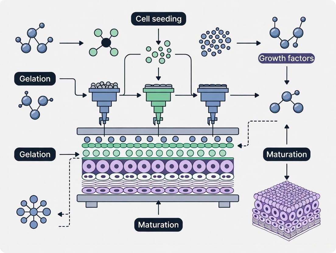
Defining Multi-Material Bioprinting and Its Core Objectives
Multi-material bioprinting is an advanced additive manufacturing technique that constructs cell-laden structures using multiple distinct bioinks within a single fabrication process. The primary objective of this technology is to create complex, heterogeneous, and biomimetic tissues that closely resemble the spatial and functional heterogeneity of native biological tissues [4]. This approach represents a paradigm shift from conventional top-down tissue engineering methods, embracing instead a bottom-up strategy where complex tissues are assembled from engineered building blocks, potentially replicating native tissue microarchitecture and function [4].
The core challenge in tissue engineering lies in replicating the intricate architectural and cellular complexity found in natural tissues, which often demands the fabrication of multi-material and multi-cellular constructs. This complexity introduces significant challenges in material compatibility, cellular integration, and structural stability, particularly when aiming to replicate intricate tissue architectures such as vascular networks or organ-specific microenvironments [4]. Multi-material bioprinting addresses these challenges through precise spatial control over material composition and cell placement.
Key Technological Approaches and Performance Characteristics
Multiple bioprinting modalities have been developed to address the challenges of multi-material fabrication, each with distinct advantages and limitations. The integration of microfluidics has emerged as a particularly transformative development, enabling enhanced control over material flow, mixing, and deposition at the microscale [4]. The table below summarizes the key performance characteristics of major multi-material bioprinting technologies:
Table 1: Performance Characteristics of Multi-Material Bioprinting Technologies
| Technology Type | Spatial Resolution | Key Advantages | Material Compatibility | Structural Strength |
|---|---|---|---|---|
| Microfluidic Bioprinting | Tens to hundreds of micrometers [4] | Precise material switching, gradient formation, low shear stress [4] | Multi-material bioinks, hydrogels [4] | Varies with crosslinking method |
| Material Jetting | 16μm layer thickness [15] | High color fidelity, smooth surfaces [15] | Photopolymer resins [15] | Medium (50-60 MPa tensile strength) [15] |
| Multi-color FDM/FFF | 100-300μm layer thickness [15] | High strength, economical [15] | Thermoplastic filaments [15] | High (50-72 MPa tensile strength) [15] |
| Binder Jetting | 100μm layer thickness [15] | Cost-effective for large models [15] | Powder materials (gypsum, nylon) [15] | Low (requires adhesive reinforcement) [15] |
Microfluidic bioprinting systems, often conceptualized as "printhead-on-a-chip" or "lab-on-a-tip" technologies, leverage several advantages including miniaturization, low reagent volumes, laminar flow regimes due to low Reynolds numbers, decreased diffusion times, and dominant surface tension and capillary forces [4]. These systems have enhanced various bioprinting modalities including extrusion-based, coaxial, droplet-based, light-based, and voxel-based bioprinting [4].
Experimental Protocol: Embedded Bioprinting of Multi-Layered Arterial Tissues
This protocol describes the fabrication of multilayered arterial tissues with controlled cellular alignment using embedded multi-material bioprinting approaches.
Materials Preparation
Table 2: Research Reagent Solutions for Arterial Model Bioprinting
| Reagent/Material | Function | Specifications |
|---|---|---|
| Bioink Formulation | Primary structural and cellular scaffold | Typically hydrogel-based (e.g., gelatin methacryloyl, alginate) with tuned viscoelastic properties |
| Support Bath Matrix | Provides temporary environment for embedded printing | Yield-stress fluid such as microparticle-filled suspensions or polymer networks |
| Crosslinking Agent | Induces bioink solidification | Ionic crosslinkers (e.g., CaCl₂ for alginate) or photoinitiators for light-cured systems |
| Cell Culture Medium | Maintains cellular viability during and post-printing | Cell-type specific medium with appropriate growth factors and supplements |
Workflow and Methodology
The following diagram illustrates the complete experimental workflow for creating multilayered arterial tissues:
Detailed Procedural Steps
Material Preparation Phase
- Bioink Formulation: Prepare primary bioink components according to targeted tissue characteristics. For arterial models, this typically involves hydrogel precursors with tuned mechanical properties to support vascular smooth muscle function [16].
- Support Bath Preparation: Fabricate yield-stress support bath materials that enable embedded printing while providing temporary structural support during the printing process.
- Cell Culture Expansion: Expand relevant cell types (e.g., vascular smooth muscle cells, endothelial cells) to appropriate confluence and viability for integration with bioink formulations.
Simulation and Planning Phase
- Flow Rate Prediction: Utilize computational models to predict optimal bioink flow rates, accounting for temperature-dependent viscosity changes and shear-thinning behavior [16].
- 3D Print Path Design: Create precise toolpaths based on targeted tissue characteristics, including layer-by-layer deposition patterns that promote cellular alignment in multilayered structures [16].
Embedded Bioprinting Execution
- Multi-layer Deposition: Sequentially deposit bioink materials within the support bath according to the predetermined toolpaths, constructing the arterial wall architecture layer by layer.
- Cellular Alignment Control: Implement printing parameters that enhance vascular smooth muscle cell alignment, modulating contractile and synthetic pathways through mechanical cues [16].
- Controlled Crosslinking: Apply appropriate crosslinking mechanisms (thermal, ionic, or photochemical) to stabilize the printed structure while maintaining cellular viability.
Biological Characterization
- Functional Assessment: Evaluate vascular smooth muscle contractile function and responsiveness to pharmacological agents.
- Structural Analysis: Characterize tissue morphology, extracellular matrix composition, and cellular organization using histological and immunohistochemical methods.
Microfluidic Printhead Design for Multi-Material Capability
The integration of microfluidics enables sophisticated multi-material capabilities through specialized printhead designs. The following diagram illustrates a conceptual microfluidic printhead system:
This microfluidic approach enables several key functionalities:
- Real-time Material Switching: Rapid alternation between different bioinks during the printing process to create discrete regional variations in material composition [4].
- On-demand Material Blending: Controlled mixing of multiple bioink precursors to create intermediate compositions with tailored properties [4].
- Spatial Gradient Generation: Establishment of continuous concentration gradients of materials, cells, or bioactive factors through controlled laminar flow and diffusion phenomena [4].
- Shear Stress Reduction: Creation of cell-friendly environments that minimize shear stress during the printing process, enhancing cellular viability and functionality [4].
Applications in Complex Tissue Architecture
Multi-material bioprinting enables several advanced applications in tissue engineering and drug development:
- Tissue Heterogeneity and Vascularization: Creation of constructs with region-specific biological properties and integrated vascular networks for nutrient transport [4].
- Tumor Microenvironment Recapitulation: Fabrication of sophisticated cancer models with heterogeneous cell populations and extracellular matrix compositions for drug screening [4].
- Cellular Microfibers: Generation of continuous fiber structures with controlled core-shell architectures and encapsulated cells for tissue assembly [4].
- Organ-on-a-Chip Systems: Integration of bioprinted tissues with microfluidic perfusion systems to create more physiologically relevant models for drug testing [4].
The protocol for arterial tissue fabrication described in Section 3 exemplifies how multi-material approaches can create structures with anatomical relevance, particularly through the control of cellular alignment patterns that enhance tissue-specific function [16].
Multi-material bioprinting represents a significant advancement in tissue engineering, enabling the fabrication of complex, heterogeneous constructs that better mimic native tissues. The technology's core objectives focus on replicating spatial and functional heterogeneity through precise control over material composition and cellular organization. As microfluidic integrations and other technical innovations continue to evolve, multi-material bioprinting is poised to transform regenerative medicine, disease modeling, and drug development by providing more physiologically relevant tissue models. Future directions will likely focus on enhancing scalability, standardizing protocols, and simplifying workflows to broaden accessibility and adoption across the research community [4].
The ultimate goal of three-dimensional (3D) in vitro models is to reproduce physiologically and biologically realistic human model systems outside the body. In the human body, the vascular network represents a hierarchical organization that serves for the efficient exchange of nutrients and oxygen and for the removal of wastes within and between tissues and organs. The presence of vascularization in engineered tissues not only maintains cell viability and function but also supports cross-talk between diverse cell and tissue types, effectively mimicking human biological responses. Thus, engineering functional vasculature is a prerequisite for the successful engineering of physiologically relevant in vitro models [17].
Overcoming the challenge of vascularization represents a significant bottleneck in advancing tissue engineering. Without vasculature, the size and complexity of an engineered tissue is limited, as the lack of nutrition and accumulation of waste will inevitably lead to cell death in bioprinted tissue structures. This limitation has driven the development of sophisticated 3D bioprinting strategies that can create perfusable, hierarchical vascular networks within engineered tissues, enabling applications from disease modeling to regenerative medicine [17] [18].
Multi-Material Bioprinting Strategies for Vascularization
Advanced Bioprinting Techniques for Vascular Networks
Multiple bioprinting strategies have been developed to vascularize in vitro tissues by spatially controlled patterning of vascular precursors or generating readily perfusable vascular structures. The table below summarizes the major 3D bioprinting strategies for developing vascular structures [17].
Table 1: Major 3D Bioprinting Strategies for Vascular Structure Development
| Bioprinting Strategy | Description | Key Benefits for Vascularization |
|---|---|---|
| Coordinated Patterning | Spatial arrangement of cell-laden inks to produce 3D constructs with interconnected pre-vascular networks | Precise spatial localization of cell types and bioactive molecules; high design flexibility [17] |
| Sacrificial Printing | Deposition of fugitive ink followed by casting and removal to create endothelialized channels | Creates perfusable microchannels; high freedom in designing channel geometries and size ranges [17] |
| Embedding Printing | Extrusion of ink into a liquid suspension bath to support printed filaments during fabrication | Improves printability of soft bioinks; enhances structural integrity with high resolution [17] |
| Coaxial Printing | Simultaneous extrusion of different materials through core/shell configuration to create hollow tubes | Direct printing of freestanding tubular structures with controllable diameter and wall thickness [17] |
| Scaffold-Free Mandrel | Using a rotating mandrel to create tubular structures without artificial scaffolds | Enables high cell density with low foreign body response; omits long culturing times [18] |
The Scaffold-Free Approach for Vascular Conduits
A scaffold-free approach using a rotating mandrel method has been successfully employed to create functional vascular conduits. This method circumvents limitations associated with artificial scaffolds, including potential immune responses and the challenge of matching scaffold degradation rates with tissue formation. By using a high cell concentration and scaffold-free techniques, the lengthy culturing times typically required after bioprinting can be significantly reduced [18].
In practice, this approach has been used to bioprint a rat aorta using rat fibroblasts and smooth muscle cells. The bioink contained smooth muscle cells (SMC) and fibroblasts (FC)—the elastic smooth muscle cell and fibroblast mixture layer mimics the tunica media, and the layer of fibroblasts mimics the tunica adventitia. The resulting 3D-bioprinted aortas were well-tolerated when implanted into rats, showed successful integration into native vasculature, and demonstrated physiological behavior of a native vessel [18].
Protocol: Bioprinting a Functional Vascular Conduit
Bioink Preparation and Formulation
This protocol details the methodology for creating an implantable vascular conduit using a scaffold-free rotating mandrel approach, based on successful implantation studies in animal models [18].
Table 2: Bioink Formulation for Vascular Conduit Bioprinting
| Component | Specification | Function |
|---|---|---|
| Hyaluronic Acid | From HyStem-C Kit | Provides compression strength, allows cell motility and adhesion [18] |
| Gelatin | From HyStem-C Kit | Contains RGD motifs for cell attachment; promotes cell growth [19] [18] |
| PEGDA | Polyethylene glycol diacrylate from HyStem-C Kit | Forms covalent bonds during cross-linking; provides long-term stability [19] [18] |
| Smooth Muscle Cells | Rat venous SMCs; passage ≤10 | Forms tunica media layer; 70% of cellular composition (42×10⁶ cells) [18] |
| Fibroblasts | Rat aortic FCs; passage ≤10 | Forms tunica adventitia layer; 30% of cellular composition [18] |
| Cell Density | 100×10⁶ cells/mL | High cell density to support scaffold-free approach [18] |
Preparation Steps:
- Culture rat venous SMCs and rat aortic FCs in individual flasks, harvesting at passage 10 or less upon reaching 80-90% confluence.
- Prepare hydrogel precursor using the HyStem-C Kit according to manufacturer specifications.
- Encapsulate cells at a density of 100×10⁶ cells/mL in the crosslinked hydrogel mixture, maintaining the 70:30 SMC:FC ratio.
- Prepare two separate bioinks with identical composition except for cell type: one with SMCs and one with FCs for layered deposition.
Bioprinting Process and Parameters
The following workflow outlines the complete process for bioprinting vascular conduits using a rotating mandrel system:
Critical Bioprinting Parameters:
- Printing Temperature: Maintain at 20-24°C throughout the printing process to ensure optimal hydrogel viscosity and cell viability.
- Cross-linking Protocol: Employ dual-crosslinking approach:
- Layer Height: 50-300 μm, depending on vascular wall thickness requirements
- Printing Speed: 1-5 mm/s, optimized to balance structural fidelity and cell viability
- Post-printing Maturation: Culture in bioreactor with dynamic flow conditions for 7-14 days to promote tissue maturation
Quality Assessment and Functional Validation
Rigorous assessment of bioprinted vascular constructs is essential before application in disease modeling or implantation:
Structural Integrity Tests:
- Uniaxial tensile testing to determine mechanical properties and compare to native vessel
- Burst pressure measurement to assess resistance to physiological pressures
- Suture retention strength testing to evaluate surgical handling capabilities
Biological Function Validation:
- Cell viability assessment via live/dead staining at 24, 48, and 72 hours post-printing
- Immunohistochemistry for tissue-specific markers (α-SMA for SMCs, vimentin for fibroblasts)
- Permeability assays using fluorescent dextrans of varying molecular weights
- In vivo implantation in animal models with periodic patency checks via Doppler ultrasound
Application in Disease Modeling and Drug Screening
Engineering Physiological and Pathological Models
Vascularized tissue models created through multi-material bioprinting enable more accurate study of human physiology and pathology. These models hold promise as alternatives to conventional cell cultures or animal models for translational application to model human physiology/pathology and drug screening [17].
Cancer Metastasis Models: Multi-material stereolithography has been used to construct simplified models of intratumoral heterogeneity with two separate sub-populations of cancer cells, which together grow over 14 days to form a dense regional interface. These models appropriately develop invasive protrusions in response to hTGF-β1, demonstrating phenotypically appropriate behaviors that enable study of tumor invasion [20].
Cardiovascular Disease Models: Bioprinted vascular structures can replicate the pathophysiology of conditions like atherosclerosis, which is characterized by buildup of plaque in the vessel lumen, resulting in stiffening of the arterial wall. These models allow for studying the progression of stenosis and ischemic injury in a controlled environment [18].
High-Content Screening Applications
The reproducibility and physiological relevance of bioprinted vascularized tissues make them valuable platforms for drug discovery. Key applications include:
- Drug Permeability Studies: Assessing compound transport across endothelial barriers
- Toxicity Screening: Evaluating drug candidate effects on vascular integrity and function
- Angiogenesis Inhibition/Activation: Testing pro- or anti-angiogenic compounds in physiologically relevant contexts
- Metastasis Inhibition: Screening compounds that block tumor cell extravasation through vascular walls
The Scientist's Toolkit: Essential Research Reagents
Table 3: Essential Research Reagents for Vascular Tissue Bioprinting
| Reagent Category | Specific Examples | Function in Bioprinting |
|---|---|---|
| Structural Hydrogels | Alginate (Alg), Carboxymethyl Cellulose (CMC), Gelatin Methacrylate (GelMA) | Provides 3D scaffold for cell encapsulation; optimal formulations include 4% Alg–10% CMC–GelMA (8-16%) [19] |
| Photoinitiators | LAP (Lithium phenyl-2,4,6-trimethylbenzoylphosphinate) | Initiates polymerization when exposed to light; enables UV crosslinking of methacrylated bioinks [21] [20] |
| Crosslinkers | CaCl₂ for ionic crosslinking; UV light for covalent bonds | Enables hydrogel solidification; dual-crosslinking provides variable stiffness [19] |
| Vascular Cell Sources | Endothelial cells, Smooth Muscle Cells (SMCs), Fibroblasts (FCs) | Recapitulates native vessel composition; forms intact endothelium, media, and adventitia layers [18] |
| Support Materials | Agarose, CELLINK Start | Acts as fugitive ink for sacrificial printing or support material for complex structures [21] |
| Basement Membrane Matrix | Matrigel | Provides complex extracellular matrix environment; supports capillary formation and cell differentiation [21] |
Future Perspectives and Challenges
The field of vascularized tissue bioprinting continues to evolve with several emerging trends. The integration of artificial intelligence and real-time monitoring systems represents a significant advancement, enabling rapid identification of print defects and adaptive correction during the printing process. This approach improves inter-tissue reproducibility and enhances resource efficiency by limiting material waste [22].
However, challenges remain in replicating the full complexity of native vasculature, including its hierarchical organization, mechanical properties, and physiological functionality. Future work must focus on improving vascular maturity, ensuring long-term stability, and enabling seamless integration with host tissues upon implantation. As these challenges are addressed, bioprinted vascularized tissues will become increasingly valuable for both basic research and clinical applications, potentially revolutionizing how we model diseases, screen drugs, and ultimately perform regenerative medicine.
Bioprinting Technologies and Bioinks for Architecturally Complex Tissues
Within the broader context of advancing multi-material bioprinting for complex tissue architecture research, selecting the appropriate fabrication modality is paramount. The fundamental challenge in this field lies in replicating the intricate spatial heterogeneity and biomechanical properties of native human tissues. Extrusion-based, stereolithography (SLA), and projection-based bioprinting have emerged as leading technologies, each offering distinct capabilities and facing specific limitations in the pursuit of manufacturing biologically relevant constructs. This application note provides a comparative analysis of these three core bioprinting modalities, framing them as essential tools for researchers and scientists focused on drug development and complex tissue modeling. The content is structured to deliver actionable, quantitative data and detailed protocols to inform experimental design and technology selection for multi-material biofabrication projects.
Technology Comparison and Quantitative Analysis
The core bioprinting technologies operate on different physical principles, which directly influences their performance in key metrics critical to tissue engineering: printing efficiency, precision, and cell viability. A fundamental trade-off exists among these parameters; optimizing for one often compromises another [23]. The following table summarizes the quantitative performance characteristics of each modality.
Table 1: Quantitative Performance Comparison of Bioprinting Modalities
| Performance Metric | Extrusion-Based | Stereolithography (SLA) | Projection-Based (PBP) |
|---|---|---|---|
| Basic Patterning Unit | Line (1D Filament) [23] | Point/Vector (Laser) or Surface (DLP) | Surface (2D Plane) [24] |
| Printing Efficiency | 0.00785–62.83 mm³/s [23] | Varies (Lower for laser scanning) | 0.648–840 mm³/s [23] |
| Theoretical Resolution | ~100 μm [24] | ~10-50 μm | ~10-25 μm [24] [25] |
| Minimum Feature Size | 100 μm [23] | <10 μm (Laser), ~25 μm (DLP) [25] | ~2 μm [23] |
| Cell Viability | 40–90% [23] | High (Limited shear stress) | High (Limited shear stress) |
| Key Advantage | High Cell Density, Multi-material Feasibility [26] | High Resolution, Structural Fidelity [20] | Highest Resolution/Manufacturing Time Ratio [24] |
| Key Limitation | High Shear Stress, Nozzle Clogging [23] [27] | Material Optical Properties, Potential Cytotoxicity [23] | Material Interface Control, Cross-contamination [24] |
Analysis of Comparative Data
- Extrusion-Based Bioprinting excels in depositing high-viscosity bioinks and achieving high cell densities, but its resolution is limited by nozzle diameter, and the associated shear stress can significantly impact cell viability [23] [27]. Its efficiency can span a wide range depending on nozzle size and printing speed.
- Stereolithography (SLA), particularly digital light processing (DLP), offers high resolution and excellent structural fidelity by curing layers simultaneously, minimizing the structural seams and voids common in extrusion methods [20]. However, it imposes strict requirements on the optical properties of bioinks (e.g., light transmittance, photosensitivity) and the potential chemical toxicity of photoinitiators must be carefully managed [23].
- Projection-Based Bioprinting (PBP), a form of vat polymerization, boasts the highest resolution-to-manufacturing time (RTM) ratio among the technologies, a key metric for combining precision with efficiency [24]. Its primary challenge lies in managing material interfaces and preventing cross-contamination during multi-material printing, which requires sophisticated rinsing and cleaning protocols [24] [28].
Experimental Protocols for Multi-Material Bioprinting
The following protocols outline standardized procedures for multi-material fabrication using each modality, designed to ensure high fidelity and minimize cross-contamination.
Protocol: Multi-Material Extrusion Bioprinting
Objective: To fabricate a heterogeneous tissue construct using a multi-nozzle extrusion bioprinter. Applications: Creating anisotropic constructs such as osteochondral tissue or vascularized tissue models [26].
Bioink Preparation:
- Formulate bioinks according to architectural requirements. Natural polymers (e.g., Gelatin, Hyaluronic Acid) are preferred for bioactivity, while synthetic polymers (e.g., PCL, PLA) provide mechanical robustness [26].
- Adjust bioink viscosity to ensure printability, balancing high viscosity for structural stability against lower viscosity for higher cell viability [23].
Printer Setup:
- Load individual bioinks into separate syringes fitted onto independent printheads.
- Calibrate the nozzle alignment and height for all printheads to ensure precise spatial deposition.
- Set the printing stage temperature to 4-10°C to aid in the initial gelation of thermosensitive bioinks.
Printing Process:
- Use a CAD model derived from medical imaging (e.g., MRI, CT) to guide deposition [26].
- Optimize printing parameters: Nozzle pressure (10-150 kPa for pneumatic systems) and print speed (5-20 mm/s) are critical and must be tuned for each bioink to minimize shear-induced cell damage [23] [26].
- For core-shell structures, employ a coaxial nozzle to simultaneously extrude different materials.
Post-Processing:
- Crosslink the printed construct immediately after deposition using appropriate methods (e.g., UV light for photocrosslinkable bioinks, ionic crosslinking for alginate).
- Transfer the crosslinked construct to a bioreactor for maturation, providing necessary biochemical and mechanical stimulation.
Protocol: Multi-Material Stereolithography Bioprinting
Objective: To create a high-resolution, heterogeneous 3D hydrogel construct with discrete cellular and acellular domains. Applications: Cancer microenvironment models, interface tissue engineering (e.g., skin-to-muscle) [20].
Bioink Preparation:
- Prepare photopolymerizable bioinks (e.g., GelMA, PEGDA) with a photoinitiator (e.g., LAP at 0.1-0.5% w/v).
- Ensure bioinks are optically clear for efficient UV penetration. Filter-sterilize if incorporating cells.
System Setup:
Printing and Material Switching:
- Lower the build platform into the first bioink vat, creating a thin layer for exposure.
- Project the UV light pattern to crosslink the first material. Adhesion should be to the build platform, not the vat.
- Lift the platform and active structure out of the vat.
- Rinsing Step: Move the platform to a washing station and manually or automatically rinse with 2-5 mL of PBS (optionally containing dilute subsequent photopolymer at 2.5-10 wt% to improve lamination) to remove residual bioink [20]. Wick away excess saline.
- Move the platform into the next bioink vat and repeat the exposure and rinsing process for each material and layer.
Post-Processing:
- After the final layer, perform a final rinse with sterile PBS.
- Culture the construct in appropriate media, changing regularly to remove any leached photoinitiator.
Protocol: Multi-Material Projection-Based Bioprinting (PBBP)
Objective: To achieve standardized, high-fidelity, and high-resolution printing of composite structures using bioinks with diverse mechanical properties [24] [28]. Applications: Reconstruction of intricate biological structures with soft-hard tissue junctions, such as bone-cartilage interfaces.
Bioink Preparation and Characterization:
- Select bioinks based on a "bonding rulebook" derived from fracture energy analysis to ensure compatibility and strong interfacial bonding between materials with different stiffnesses [28].
- Characterize the photo-cross-linking behavior (e.g., curing time, energy dose) for each bioink to standardize parameters.
System Setup:
- Utilize a multi-material PBBP system equipped with a vat-switching device (supporting up to 6 materials), a fluid rinsing system, and a negative-pressure drying device [24].
- Calibrate the optical system (e.g., DMD) to ensure precise resolution (e.g., 25 μm).
Synchronized Printing and Cleaning:
- For each layer, the system positions the build platform over the designated bioink vat.
- After exposure, the platform lifts, and the vat switches.
- Synergistic Cleaning: Implement a "fluid-controlled rinsing with negative pressure-assisted capillary adsorption" strategy. This involves a precise fluid flush followed by negative pressure to eliminate residual liquid from porous structures, effectively preventing cross-contamination [28].
Quality Control:
- Use the system's integrated visual observation module for real-time monitoring.
- Employ a standardized multi-material print resolution evaluation model to assess printing accuracy and identify error sources [24].
Visualizing Workflows and System Architectures
The following diagrams illustrate the logical workflows and key system components for the featured bioprinting modalities, highlighting their approach to multi-material integration.
Figure 1: Multi-Material Bioprinting Workflow Comparison. This diagram outlines the generalized workflows for the three main bioprinting modalities, highlighting the distinct approaches to multi-material fabrication: multi-nozzle deposition for extrusion and vat-switching for SLA/PBP.
The Scientist's Toolkit: Essential Research Reagents and Materials
Successful multi-material bioprinting requires careful selection of materials and reagents. The following table details key components for constructing heterogeneous tissue models.
Table 2: Essential Research Reagent Solutions for Multi-Material Bioprinting
| Category | Item | Function & Application Notes |
|---|---|---|
| Base Biomaterials | Gelatin Methacryloyl (GelMA) | A photocrosslinkable hydrogel derived from ECM; highly tunable mechanical properties and excellent cell responsiveness [23] [25]. |
| Poly(ethylene glycol) diacrylate (PEGDA) | A synthetic, bioinert hydrogel; often used as a mechanically stable frame or to create controlled microenvironments [20] [25]. | |
| Alginate | A natural polymer used extensively in extrusion bioprinting; rapidly crosslinks with divalent cations (e.g., Ca²⁺) [26]. | |
| Crosslinking Agents | Photoinitiators (e.g., LAP) | Absorbs light energy to generate free radicals, initiating the crosslinking of photopolymerizable bioinks (e.g., GelMA, PEGDA) [20]. |
| Calcium Chloride (CaCl₂) | Ionic crosslinker for alginate-based bioinks; can be applied as a post-print mist or bath or co-extruded in coaxial setups [26]. | |
| Cell Culture & Analysis | Vascular Endothelial Growth Factor (VEGF) | A key biochemical cue to promote vascularization within bioprinted constructs; can be encapsulated in hydrogels for sustained release [25]. |
| Cell Viability/Cytotoxicity Assay Kits | Essential for quantifying the percentage of live cells post-printing (e.g., Calcein AM/EthD-1 live/dead staining) to optimize printing parameters [23]. | |
| Hardware Components | Microfluidic Printhead | A "printhead-on-a-chip" device enabling real-time switching, mixing, and gradient formation of multiple bioinks during printing [4]. |
| Digital Micro-mirror Device (DMD) | A spatial light modulator used in SLA/PBP to dynamically project high-resolution patterns for layer-by-layer crosslinking [24] [25]. |
Multi-Material Stereolithography (MMSLA) represents a significant advancement in additive manufacturing for tissue engineering, enabling the fabrication of complex, heterogenous tissue constructs with high-resolution interfaces. As a subset of vat polymerization, MMSLA builds upon the principles of stereolithography (SLA) by incorporating multiple photoresponsive bioinks into a single printing process [29] [30]. This capability is crucial for replicating the intricate architectural and compositional nuances of native tissues, where sharp transitions between different cell types and extracellular matrices are essential for proper biological function [3]. The technology's exceptional resolution, typically ranging from 5-50 micrometers, allows for precise spatial control over material placement, facilitating the creation of sophisticated tissue models that more accurately mimic in vivo conditions for research and drug development applications [29].
The evolution of MMSLA technology coincides with a paradigm shift in tissue engineering toward creating biomimetic environments that recapitulate the complex microenvironments found in living organisms [3]. Traditional single-material bioprinting approaches face limitations in reproducing the natural interfaces between different tissue types, such as those between vascular networks and parenchymal tissues, or the graduated transition from bone to cartilage in osteochondral constructs [31]. MMSLA addresses these challenges by enabling the fabrication of constructs with spatially controlled biochemical and mechanical properties, making it particularly valuable for creating advanced in vitro models for drug screening, disease modeling, and the development of implantable tissue constructs [29] [32].
Comparative Analysis of Bioprinting Technologies
The landscape of 3D bioprinting technologies encompasses several distinct approaches, each with unique advantages and limitations for specific applications in tissue engineering. Understanding the relative capabilities of these technologies provides essential context for appreciating the specific value proposition of MMSLA in creating high-resolution interfaces.
Table 1: Comparison of Major 3D Bioprinting Technologies
| Technology | Resolution | Speed | Cell Viability | Material Versatility | Key Applications |
|---|---|---|---|---|---|
| Inkjet-based | 20-100 μm [30] | Moderate [29] | >85% [29] | Low viscosity bioinks only [29] | High-throughput screening, patterned cell deposition [29] |
| Extrusion-based | ≥100 μm [29] | Slow (10-50 μm/s) [29] | 40-95% (shear-dependent) [30] | High viscosity materials, high cell densities [29] [30] | Organoids, vascularized tissues, bone/cartilage scaffolds [29] [3] |
| Laser-assisted | Single cell (∼10 μm) [30] | Very slow [30] | >95% [30] | Limited by ribbon preparation [30] | High-precision cell patterning, stem cell niches [30] |
| SLA/DLP-based | <20-50 μm [29] [30] | Fast (volumetric) [29] | >90% (UV exposure-dependent) [30] | Photocrosslinkable hydrogels [29] | High-resolution scaffolds, microfluidic devices, complex tissue interfaces [29] |
As evidenced in Table 1, MMSLA and related light-based bioprinting technologies offer a favorable combination of high resolution and printing speed compared to other modalities. The digital nature of SLA-based processes enables exceptional precision in material placement, which is paramount for creating defined interfaces between different biomaterials and cell types [29]. Furthermore, the layerless continuous printing capability of advanced DLP systems significantly reduces printing time and eliminates artificial interfaces between layers, resulting in constructs with improved mechanical integrity [29]. These characteristics make MMSLA particularly suitable for applications requiring precise spatial control, such as recreating the complex tissue interfaces found in organ-on-a-chip systems, vascular networks, and multi-tissue constructs [31].
MMSLA Experimental Protocol for Complex Tissue Interfaces
Equipment and Reagent Setup
The successful implementation of MMSLA requires careful preparation of both hardware and bioink components to ensure reproducible fabrication of high-resolution interfaces.
Table 2: Essential Research Reagent Solutions for MMSLA
| Reagent/Material | Composition | Function | Example Formulation |
|---|---|---|---|
| Photocrosslinkable Hydrogels | GelMA, PEGDA, Hyaluronic acid methacrylate [29] [3] | Structural scaffold providing biomechanical support and cell adhesion sites | 5-15% (w/v) GelMA with 0.1-0.5% (w/v) LAP photoinitiator [3] |
| Cell Suspensions | Primary cells, stem cells, or cell lines in culture medium [29] [3] | Biological component for tissue formation and function | 1-10 million cells/mL in bioink [3] |
| Photoinitiators | Lithium phenyl-2,4,6-trimethylbenzoylphosphinate (LAP), Irgacure 2959 [3] | Initiate polymerization upon light exposure | 0.1-0.5% (w/v) in hydrogel precursor solution [3] |
| Support Baths | Carbopol, gelatin microparticles, Pluronic F127 [31] | Temporary support for overhanging structures during multi-material printing | 1-3% (w/v) Carbopol in PBS [31] |
| Functional Additives | RGD peptides, growth factors, ECM proteins [3] | Enhance bioactivity and direct cell behavior | 0.1-1 mg/mL RGD peptides in bioink [3] |
Prior to printing, the MMSLA system requires calibration and preparation. The digital light processing (DLP) engine, typically comprising a digital micromirror device (DMD) chip with approximately two million micromirrors, must be calibrated to ensure precise pattern projection [29]. The bioink reservoirs should be filled with respective photopolymerizable bioinks, taking care to minimize bubble formation. For multi-material printing, a cleaning mechanism between material swaps is essential to prevent cross-contamination [29]. The building platform should be leveled and the z-axis precision verified to ensure dimensional accuracy throughout the printing process.
Multi-Material Printing Procedure
The following protocol details the step-by-step process for fabricating a complex tissue construct with high-resolution interfaces using MMSLA:
Digital Design and Slicing: Create a 3D model of the desired tissue construct using computer-aided design (CAD) software or medical imaging data (e.g., CT, MRI) converted to STL format [3]. For multi-material constructs, assign specific regions to different materials using appropriate software features. Slice the model into sequential layers corresponding to the printing resolution, typically 10-50 μm thick [29].
Bioink Preparation and Loading: Prepare each photopolymerizable bioink according to Table 2 formulations. Gently mix cell suspensions into hydrogel precursor solutions at the recommended cell densities. Centrifuge at low speed (200-500 g) to remove air bubbles. Load each bioink into separate reservoirs of the MMSLA system, ensuring temperature control if necessary (e.g., maintaining 4-10°C for thermosensitive materials).
Initial Layer Fabrication: Lower the build platform into the first bioink reservoir until a layer thickness of 25-100 μm is achieved. Project the first slice pattern using UV light (typically 365-405 nm) at an intensity of 5-20 mW/cm² for 5-30 seconds exposure time, depending on bioink photosensitivity [29]. Retract the build platform to separate from the resin tank.
Multi-Material Switching and Interface Formation: For layers requiring material transitions, implement the following sequence:
- Move the build platform to the cleaning station and perform a gentle wash using appropriate buffer solution.
- Translate the platform to the subsequent bioink reservoir.
- Lower the platform into the new bioink, ensuring precise alignment with the previously printed layers.
- Project the next slice pattern, paying particular attention to interface regions where materials meet.
- Repeat this process for each layer, with material switches occurring as dictated by the digital design.
Post-Printing Processing: Upon completion of the final layer, carefully retrieve the construct from the build platform. Rinse with sterile PBS to remove uncrosslinked material and processing solutions. Perform additional post-crosslinking if necessary using a broad UV exposure (2-5 minutes at 5-10 mW/cm²) to ensure complete polymerization.
Cell Culture and Maturation: Transfer the construct to cell culture medium and maintain under standard culture conditions (37°C, 5% CO₂). Change medium every 24-48 hours, monitoring cell viability and tissue maturation over time. For vascularized constructs, consider implementing flow conditions using bioreactors to enhance tissue development and functionality [31].
Diagram 1: MMSLA fabrication workflow for complex tissue constructs with high-resolution interfaces. The process highlights the critical material switching steps that enable multi-material capability.
Quality Assessment and Characterization
Rigorous characterization of the printed constructs is essential to validate the formation of high-resolution interfaces and ensure biological functionality:
Structural Analysis: Employ scanning electron microscopy (SEM) to examine the microstructure and interface integrity between different materials [33]. Utilize micro-computed tomography (μCT) for non-destructive 3D analysis of internal architecture and interface continuity.
Mechanical Testing: Perform nanoindentation at interface regions to measure spatial variations in mechanical properties. Conduct tensile tests to evaluate interfacial strength and durability.
Biological Assessment: Monitor cell viability at interface regions using live/dead staining protocols. Evaluate cell morphology and organization through immunohistochemistry and confocal microscopy. For functional assessments, measure tissue-specific markers and metabolic activity.
Applications in Complex Tissue Engineering
MMSLA technology enables the fabrication of sophisticated tissue models with anatomically relevant interfaces that are crucial for advancing drug development and tissue engineering research.
Vascularized Tissue Constructs
Creating functional vasculature within engineered tissues represents one of the most significant challenges in tissue engineering. MMSLA facilitates the fabrication of complex, hierarchical vascular networks through precise spatial patterning of endothelial cells and supportive pericytes within a tissue-specific ECM [31]. The technology enables the creation of vessel structures with decreasing diameters from arterioles to capillaries, mimicking the natural vascular architecture essential for nutrient and oxygen delivery throughout thick tissue constructs [31]. These vascularized tissues can maintain cell viability in regions nearly ten times thicker than avascular constructs, addressing a critical limitation in engineering clinically relevant tissue volumes [31].
Organ-on-a-Chip and Disease Models
The high resolution of MMSLA makes it ideal for creating sophisticated organ-on-a-chip systems with integrated microfluidic networks and tissue-tissue interfaces [29]. For instance, the technology has been used to create the first entirely 3D-printed heart-on-a-chip with integrated soft strain sensors that monitor tissue contractility [31]. These systems can incorporate multiple tissue types separated by permeable membrane-like interfaces that mimic physiological barriers in the human body, such as the blood-brain barrier or alveolar-capillary interface [29]. The capacity to precisely control these interfaces enables more accurate modeling of drug transport and disease processes, providing valuable platforms for pharmaceutical screening and disease mechanism studies.
Osteochondral and Interface Tissue Engineering
MMSLA excels at fabricating constructs with graduated transitions between different tissue types, such as the interface between bone and cartilage in osteochondral tissues [3]. By strategically depositing materials with distinct mechanical and biochemical properties, MMSLA can recreate the natural zonal organization of these interface tissues, which is crucial for their functional performance [3]. The technology enables precise control over mineral concentration, collagen alignment, and growth factor distribution across the interface region, promoting the formation of continuous tissue integration rather than sharp, mechanically weak junctions.
Diagram 2: Tissue engineering applications leveraging MMSLA's capability to create high-resolution interfaces. Each application utilizes specific architectural features enabled by multi-material printing.
Technical Considerations and Optimization Strategies
Achieving high-resolution interfaces with MMSLA requires careful attention to several technical aspects throughout the printing process. The following optimization strategies can enhance interface quality and biological performance:
Interface Bonding Optimization: To ensure strong adhesion between different materials, design interdigitated or graded interfaces rather than sharp boundaries. Incorporate chemical functional groups that promote covalent bonding between layers, such as acrylate groups in both materials [3]. Adjust exposure parameters at interface regions to ensure adequate crosslinking between materials.
Resolution Enhancement: For features approaching the theoretical resolution limits of MMSLA, optimize the photoinitiator concentration and light absorption properties to minimize light scattering [30]. Utilize computed tomography-inspired optimization algorithms to account for light penetration and scattering effects during pattern projection [29].
Cell Viability Maintenance: To preserve cell viability during the printing process, carefully optimize UV exposure time and intensity, implementing multiple short exposures rather than continuous illumination for thick layers [30]. Incorporate radical scavengers in the bioink formulation to mitigate oxidative stress, and maintain physiological temperature throughout the printing process [3].
Multi-Material Stereolithography represents a transformative technology for engineering complex tissue architectures with high-resolution interfaces. By enabling precise spatial control over multiple biomaterials and cell types, MMSLA facilitates the creation of biologically relevant tissue models that more accurately mimic native tissue organization and function. The protocols and applications outlined in this document provide researchers with a framework for leveraging MMSLA capabilities in tissue engineering and drug development research. As the technology continues to evolve, advancements in bioink development, printing resolution, and vascularization strategies will further enhance our ability to recreate sophisticated tissue interfaces for both basic research and clinical applications.
The pursuit of engineering complex, biomimetic tissues demands technologies capable of replicating the intricate spatial and functional heterogeneity found in native organs. Multi-material bioprinting stands at the forefront of this challenge, aiming to fabricate constructs with precise arrangements of cells and extracellular matrix components. A significant advancement in this field is the integration of microfluidic technology with bioprinting, leading to the development of sophisticated “printhead-on-a-chip” systems [4]. These systems enable real-time material switching, gradient formation, and enhanced printing resolution by leveraging the principles of microscale fluid dynamics [4]. This capability is critical for creating complex tissue architectures, such as vascular networks and organ-specific microenvironments, which are essential for advanced research in tissue engineering, disease modeling, and drug development [4]. This protocol details the application of microfluidic bioprinting for precision deposition and dynamic switching between bioinks, providing a foundational methodology for multi-material tissue construct fabrication.
Quantitative Benchmarking of Bioink Performance
Selecting and evaluating bioinks based on quantitative performance metrics is crucial for successful bioprinting. The following criteria should be assessed to ensure cell compatibility during the printing process [34].
Table 1: Quantitative Benchmarks for Bioink Performance
| Performance Criterion | Testing Protocol Summary | Key Quantitative Metrics | Exemplary Bioink Performance |
|---|---|---|---|
| Cell Sedimentation | Incubate cell-laden bioink in printing cartridge for 1 hour; measure homogeneity [34]. | Homogeneity of cell distribution; percentage of settled cells [34]. | GelMA & RAPID inks: Prevent appreciable sedimentation.PEGDA alone: Significant cell settling [34]. |
| Cell Viability During Extrusion | Print cells at constant flow rate (e.g., 75 µL/min); immediately test membrane integrity [34]. | Percentage of cells with membrane damage post-extrusion [34]. | RAPID inks: < 4% damage.PEGDA/GelMA: < 10% damage [34]. |
| Cell Viability After Curing | Expose cells to curing conditions (e.g., light, CaCl₂) for 5 minutes; test membrane integrity [34]. | Percentage of cells damaged after curing, particularly at droplet edges [34]. | RAPID inks (CaCl₂): < 20% damage.PEGDA/GelMA (Light): > 50% damage [34]. |
Table 2: Comparison of Bioprinting Techniques for Multi-Material Fabrication
| Bioprinting Technique | Typical Resolution | Cell Viability | Suitability for Multi-Material | Key Advantages |
|---|---|---|---|---|
| Extrusion-Based | 100 - 500 µm [35] | Moderate (shear stress-dependent) [35] | High (with multi-printhead) [35] | Prints high-viscosity bioinks; large-scale constructs [35]. |
| Inkjet | 100 - 500 µm [35] | Excellent [35] | Moderate | High-speed; good for detailed patterns [35]. |
| Laser-Assisted | < 10 µm [35] | > 95% [35] | Moderate | High precision; nozzle-free [35]. |
| Stereolithography (SLA) | ~10 µm (can degrade with cell density) [35] | 70 - 90% [35] | High (with multi-wavelength) [35] | High resolution; smooth surfaces [35]. |
Experimental Protocols
Protocol 1: Microfluidic Printhead Operation for Real-Time Material Switching
This protocol describes the setup and operation of a microfluidic printhead for switching between two different bioinks during a single printing process [4].
Materials:
- Microfluidic printhead (e.g., with two inlets, one outlet).
- Bioprinter with multi-printhead capability or a single printhead driving multiple syringes.
- Bioinks A and B (e.g., GelMA-based and alginate-based).
- Pressure-based dispensing system.
- Computer with bioprinting control software.
Procedure:
- System Setup: Load Bioink A and Bioink B into separate syringes. Connect each syringe to the respective inlets of the microfluidic printhead using tubing. Ensure all connections are secure to prevent leaks.
- Software Configuration: In the bioprinting control software, designate the two syringes as different materials. For the print path, program the toolpath for the construct, specifying which material (bioink) is to be deposited in which region of the construct.
- Priming: Prime the printhead and nozzle by dispensing a small amount of each bioink sequentially to clear any air bubbles and ensure smooth flow.
- Printing Execution: Initiate the print job. The software will automatically control the pressure to the designated syringe when the toolpath requires a specific bioink. The selected bioink will flow through the microfluidic channel and be deposited from the common nozzle.
- Curing: For light-curable bioinks like GelMA, initiate crosslinking using a UV light source (e.g., 365 nm wavelength) with a photoinitiator (e.g., 0.05%–0.5% w/v LAP) immediately after each layer is deposited, or after the entire construct is printed, depending on the structural requirements [36] [37].
Protocol 2: Bioprinting a Multi-Layered Construct with GelMA/Geltrex Bioink
This protocol provides detailed steps for designing and printing a dual-layer construct, such as an endothelial-epithelial model, using CAD software and a extrusion bioprinter [36].
Materials:
- Cells: A549 (alveolar epithelial) and HUVEC (human umbilical vein endothelial cells).
- Bioink: GelMA/Geltrex mixture.
- Crosslinker: Photoinitiator (e.g., 2-Hydroxy-4'-(2-hydroxyethoxy)-2-methylpropiophenone).
- Software: TinkerCAD (or similar CAD), PrusaSlicer (or similar slicer).
- Bioprinter: Extrusion-based system (e.g., RepRap-based).
Procedure:
- Model Design:
- Slicing Setup:
- Bioink Preparation:
- Synthesize GelMA as previously described [37] or acquire commercially.
- Mix GelMA with Geltrex in culture medium at a concentration tailored to the application (e.g., 5-10% w/v GelMA) [36].
- Add photoinitiator to the mixture.
- Suspend A549 cells in the bioink for the "Bottom" layer and HUVECs for the "Top" layer, achieving a final density of approximately 50,000 cells per construct [36].
- Bioprinting:
- Load the "Bottom" layer bioink (A549-laden) into one syringe and the "Top" layer bioink (HUVEC-laden) into another.
- Use the slicer software to generate and execute the G-code for the "Bottom" layer.
- Upon completion, pause the printer, switch the syringe to the "Top" layer bioink, and resume printing to deposit the second layer.
- Crosslinking and Post-Processing:
- After each layer is deposited, expose the construct to UV light (e.g., 365 nm) for a specified duration to crosslink the GelMA.
- After printing, transfer constructs to cell culture incubator for maturation.
Workflow Visualization
Diagram 1: Microfluidic Material Switching
Diagram 2: Multi-Layer Bioprinting Workflow
The Scientist's Toolkit: Research Reagent Solutions
Table 3: Essential Materials for Microfluidic Bioprinting
| Reagent/Material | Function | Example Application Notes |
|---|---|---|
| Gelatin Methacrylate (GelMA) | Photocrosslinkable hydrogel bioink; provides biocompatibility and RGD cell-adhesion sites [36] [37]. | Degree of methacrylation and concentration tune mechanical properties. Ideal for cartilage and adipose models [36]. |
| Alginate | Polysaccharide for ionic (e.g., Ca²⁺) crosslinking; often used in composite bioinks [34] [37]. | Provides rapid gelation. Used in RAPID ink with recombinant proteins for dual-crosslinking [34]. |
| Poly(ethylene glycol) diacrylate (PEGDA) | Synthetic, photopolymerizable hydrogel; highly tunable but often requires additives for cell adhesion [34]. | Bio-inert. Cell sedimentation can be an issue without thickening agents like xanthan gum [34]. |
| Pluronic F-127 | Sacrificial support material; used in build/support configurations for printing freeform structures [37]. | Thermoreversible gel. Can be supplemented with CaCl₂ to crosslink alginate-based build materials at the interface [37]. |
| Geltrex | Basement membrane extract; enhances bioink by providing complex proteins like Laminin and Collagen IV [36]. | Mixed with GelMA to improve biological activity and better recreate natural features of the cellular microenvironment [36]. |
| Photoinitiator (e.g., LAP) | Initiates polymerization of light-curable hydrogels (e.g., GelMA, PEGDA) upon UV exposure [36] [37]. | Concentration and exposure time must be optimized to balance crosslinking efficiency and cell viability [34]. |
The extracellular matrix (ECM) is a highly sophisticated, dynamic network of macromolecules that provides not only structural support but also critical biochemical and biomechanical cues which orchestrate cellular behaviors such as adhesion, migration, proliferation, and differentiation [38] [39]. Effective tissue engineering and regenerative medicine strategies require bioinks that faithfully replicate this complex native microenvironment [40]. Advanced bioink formulations are thus engineered to mimic the ECM's composition, architecture, and functionality, serving as a foundational step towards creating physiologically relevant multi-material bioprinted tissues [4].
The design of ECM-mimicking bioinks is guided by several core principles: biocompatibility to support cell viability and function, printability to enable the fabrication of complex 3D structures, and appropriate mechanical and rheological properties that mirror the target native tissue [41] [42]. Furthermore, the bioink must act as a bioactive scaffold, facilitating essential cell-ECM interactions through integrin-mediated signaling and allowing for controlled remodeling, much like the natural matrix [39]. This document outlines the key material platforms, quantitative properties, and detailed protocols for formulating and evaluating these advanced bioinks within the context of multi-material bioprinting research.
Key Bioink Platforms for ECM Recapitulation
Natural Polymer-Based Bioinks
Natural polymers are widely utilized due to their innate bioactivity and resemblance to the native ECM.
- Collagen-based Bioinks: As the most abundant protein in the mammalian ECM, collagen, particularly Type I, is a premier choice for bioinks. It offers excellent biocompatibility and supports cell adhesion and signaling [43] [42]. A critical challenge is its low mechanical strength, which is often addressed through blending with other polymers or crosslinking. Sourcing (e.g., bovine, porcine, equine, marine, or recombinant) and extraction methods (e.g., acid-soluble or pepsin-assisted) significantly influence the collagen's properties, including its degradation rate and mechanical robustness [43].
- Alginate-Gelatin (Alg-Gel) Blends: This composite bioink combines the excellent shear-thinning properties and rapid ionic crosslinking of alginate with the thermo-reversible gelation and cell-adhesive RGD motifs of gelatin [41] [44]. The properties of Alg-Gel bioinks, including stiffness, viscosity, swelling, and degradation, can be finely tuned by varying parameters such as the polymer concentration and the ionic strength of the solvent [44]. This tunability makes it a versatile platform for optimizing both printability and biological performance.
ECM-Inspired Synthetic and Hybrid Platforms
- Cryogels: These are a class of macroporous hydrogels fabricated through a cryogelation process at sub-zero temperatures, resulting in a highly interconnected pore structure [40]. ECM-mimicking cryogels exhibit high mechanical strength, elasticity, and facilitate mass transport, making them advantageous for applications like hypoxic tumor modeling and cancer research [40].
- Decellularized ECM (dECM) Bioinks: dECM bioinks are derived from native tissues that have undergone a process to remove cellular material while preserving the native ECM's complex composition and biochemical cues [38]. This platform most closely replicates the tissue-specific microenvironment, but requires careful optimization of decellularization protocols to avoid ECM damage and ensure complete antigen removal [38].
- Hybrid Composites: These bioinks integrate natural ECM components (e.g., collagen, hyaluronic acid) with synthetic polymers (e.g., PLGA, PEG). This approach merges the bioactivity of natural materials with the tunable mechanical strength and degradation profiles of synthetic ones, offering a promising strategy for demanding tissue engineering applications [38] [39].
Table 1: Key Formulation Parameters and Their Impact on Bioink Properties
| Bioink Platform | Key Tunable Parameters | Impact on Printability | Impact on Biological Function |
|---|---|---|---|
| Alginate-Gelatin | Polymer concentration, Alg:Gel ratio, solvent ionic strength [44] | Modulates viscosity, shear-thinning, shape fidelity [41] [44] | Influences stiffness, swelling, degradation, and cell viability/proliferation [44] |
| Collagen | Concentration, pH, temperature, crosslinker type/ concentration [43] [42] | Governs gelation kinetics, structural integrity, and resolution [42] | Directly affects cell adhesion, differentiation, and tissue-specific maturation [43] |
| dECM | Tissue source, decellularization method [38] | Rheology is highly source-dependent; often requires blending for printability | Provides tissue-specific biochemical cues for enhanced phenotypic maintenance [38] |
| Cryogels | Polymer composition, freezing conditions, crosslinking [40] | Creates macroporous structures; shape fidelity is tied to cryogelation process | High porosity enhances cell infiltration and mass transport; supports hypoxia modeling [40] |
Quantitative Analysis of Bioink Properties and Performance
The following tables consolidate critical quantitative data for benchmarking and optimizing bioink formulations.
Table 2: Mechanical and Rheological Properties of Exemplary Bioink Formulations
| Bioink Formulation | Storage Modulus (G') | Viscosity (at specified shear rate) | Swelling Ratio | Degradation Profile |
|---|---|---|---|---|
| Alg-Gel (3% Gel in 4% Alg) | ~5 kPa (at operating temp) [44] | Exhibits shear-thinning [41] | Low swelling; high shape fidelity [41] | Maintains structure after 14 days incubation [41] |
| Alg-Gel (B-2 from ionic strength study) | Medium G' within test series [44] | Medium viscosity within test series [44] | Minimal swelling over 14 days [44] | Stable over culture period [44] |
| High Ionic Strength Bioink (e.g., B-4) | Lower G' within test series [44] | Lower viscosity within test series [44] | Significant swelling over 14 days [44] | Apparent degradation with flocculent precipitate at Day 14 [44] |
Table 3: Biological Performance Metrics of Optimized Bioinks
| Bioink Formulation | Cell Viability Post-Printing | Proliferation (e.g., Ki-67+ at Day 14) | Key Functional Outcomes |
|---|---|---|---|
| Alg-Gel (3% Gel in 4% Alg) | >90% at 5 days post-printing [41] | N/A | High normalized pore number (98%); excellent shape fidelity [41] |
| Alg-Gel (Optimized B-2) | >80% post-printing; modest rebound during Days 7-14 [44] | Highest rate at Day 14 vs. other formulations [44] | Facilitated cellular aggregation and glandular-lineage differentiation (K8/K18+) [44] |
| Collagen-based (optimized) | Highly dependent on crosslinking & printing process [42] | Supported by native bioactivity [43] | Promotes cell-driven remodeling and tissue-specific differentiation [43] [42] |
Experimental Protocols
Protocol 1: Formulating and Tuning Alginate-Gelatin Bioink with Varied Solvent Ionic Strength
This protocol describes a method to systematically control Alg-Gel bioink properties by varying the ionic strength of the phosphate-buffered saline (PBS) solvent, enabling the optimization of printability and stem cell behavior [44].
Research Reagent Solutions
| Item | Function |
|---|---|
| Sodium Alginate Powder | Primary polymer providing shear-thinning and ionic crosslinking. |
| Gelatin Powder (from bovine skin, Type B) | Provides thermo-reversible gelation and cell-adhesive RGD motifs. |
| Phosphate-Buffered Saline (PBS) | Biocompatible solvent; varying ionic strength tunes bioink properties. |
| Calcium Chloride (CaCl₂) | Ionic crosslinker for alginate, inducing hydrogel formation. |
| Red Food Dye | For visualization and contrast enhancement of printed constructs. |
Step-by-Step Procedure
- Solution Preparation: Prepare PBS solvents with varying ionic strengths (e.g., 0.5X, 1X, 2X). Dissolve sodium alginate powder in the PBS to a concentration of 4% (w/v). Separately, dissolve gelatin powder in the Alginate-PBS solution at varying concentrations (e.g., 1%, 2%, 3% w/v) [44].
- Bioink Processing: Vortex the Alg-Gel mixtures for one minute at 3400 rpm. Store the solutions at 37°C for 24 hours to ensure complete dissolution of the powders. To enhance visualization and remove air bubbles, add a small amount of red food dye and vortex for 30 seconds, then let the bioink rest at 37°C for 30-60 minutes [44].
- Crosslinker Preparation: Dissolve calcium chloride (CaCl₂) in PBS at a typical concentration of 2% (w/v) by vortexing for one minute. Load the solution into a syringe for co-axial printing or for post-printing crosslinking.
- Rheological Characterization: Perform rheological analysis to determine storage modulus (G') and loss modulus (G") via a frequency sweep. Conduct a viscosity test across a shear rate range of 0.1–1500 s⁻¹ to confirm shear-thinning behavior [44].
- Printability Assessment: Using a co-axial nozzle or a standard extrusion printhead, print grid structures (e.g., two-layer and six-layer). Quantify printability by measuring the pore area immediately after printing, after crosslinking, and after two days of incubation in culture medium. Calculate the normalized pore number to evaluate shape fidelity [41].
- Biological Validation: Encapsulate cells (e.g., epidermal stem cells) within the bioink and print cell-laden constructs. Culture the constructs and assess cell viability using a Live/Dead assay at days 1, 7, and 14. Evaluate proliferation (e.g., via Ki-67 staining) and monitor specific differentiation markers relevant to the target tissue over a culture period of up to 28 days [44].
Protocol 2: Development and Evaluation of a Collagen-Based Bioink
This protocol outlines the preparation, printing, and characterization of a collagen-based bioink, focusing on managing its gelation kinetics for optimal printability and biological performance [43] [42].
Research Reagent Solutions
| Item | Function |
|---|---|
| Type I Collagen Solution (e.g., from bovine tendon) | Core ECM-mimicking polymer, providing bioactivity and cell support. |
| Neutralization Solution (e.g., NaOH/HEPES) | Adjusts pH to initiate collagen fibrillogenesis and gelation. |
| Crosslinking Agent (e.g., Genipin, EDC-NHS) | Enhances mechanical integrity and stability of printed constructs. |
| DMEM/F-12 Medium | Can be used as a solvent or supplement to provide biocompatible environment. |
Step-by-Step Procedure
- Collagen Preparation: Thaw the acidic Type I collagen solution on ice. Keep all components and equipment cold to prevent premature gelation.
- Bioink Neutralization: Slowly mix the cold collagen with a pre-calculated volume of neutralization solution (e.g., 1M NaOH and HEPES buffer in PBS) to bring the pH to approximately 7.4. Gently mix to avoid introducing air bubbles. The final collagen concentration is typically adjusted to between 3-10 mg/mL depending on the target application [42].
- Optional Blending and Crosslinking: For enhanced mechanical properties, blend the neutralized collagen with a supplemental polymer (e.g., alginate, methylcellulose). To increase stability, add a crosslinking agent to the mixture. Note that crosslinking can affect gelation time and cell viability.
- Gelation Kinetics Analysis: Use a rheometer to monitor the storage modulus (G') over time at 37°C to characterize the gelation kinetics. This data is critical for determining the allowable printing time window.
- Extrusion Bioprinting: Load the neutralized, cold bioink into a temperature-controlled printing cartridge. Maintain the bioink at 4-10°C during printing to delay gelation. Use a heated print bed (e.g., 37°C) to induce gelation upon deposition, thereby improving layer adhesion and shape fidelity [43].
- Post-Printing Incubation and Analysis: After printing, incubate the constructs in culture medium at 37°C to complete gelation. Assess the structural integrity and contraction of the constructs over time. For cell-laden prints, perform viability assays (Live/Dead), immunostaining for cytoskeletal and matrix proteins, and gene expression analysis to confirm the maintenance of desired cellular phenotypes [42].
Signaling Pathways in ECM-Mimetic Environments
A critical function of an ECM-mimicking bioink is to facilitate native cell-ECM signaling, primarily through integrin-mediated pathways that direct cell fate.
Diagram 1: Integrin-Mediated Signaling in ECM Environments
Workflow for Bioink Development and Evaluation
The process from bioink design to functional validation involves iterative cycles of formulation, printing, and analysis.
Diagram 2: Bioink Development Workflow
The development of perfusable vascular networks represents a cornerstone in advancing tissue engineering and regenerative medicine. Within the broader thesis of multi-material bioprinting for complex tissue architecture, the creation of such networks is paramount for engineering large-scale, functional tissues. Native tissues are intrinsically complex and rely on hierarchical vascular networks for the delivery of oxygen and nutrients and the removal of metabolic waste [45]. Without these networks, engineered tissues face diffusion limits, leading to core necrosis and impaired function, a challenge that becomes critical for constructs thicker than a few hundred micrometers [46] [47]. Multi-material bioprinting has emerged as a powerful strategy to address this, enabling the precise spatial patterning of multiple cell types and biomaterials to create intricate, perfusable channels that mimic natural vasculature [45]. This application note details the key engineering strategies, quantitative benchmarks, and detailed protocols underpinning this transformative capability.
Key Engineering Strategies and Quantitative Analysis
Several bioprinting strategies have been developed to engineer perfusable vasculature, each with distinct mechanisms and advantages. The table below summarizes the principal approaches, their core methodologies, and key outcomes.
Table 1: Key Strategies for Engineering Perfusable Vascular Networks via Bioprinting
| Strategy | Core Mechanism | Key Advantages | Reported Outcomes |
|---|---|---|---|
| Direct Coaxial Bioprinting [48] | Uses a multilayered coaxial nozzle to extrude a hollow, cell-laden filament in a single step. A core crosslinking agent (e.g., CaCl₂) is surrounded by a bioink shell. | Single-step fabrication; creates immediately perfusable channels; high architectural order. | Supported endothelial cell spreading and proliferation; formed stable, perfusable hollow tubes. |
| Sacrificial Bioprinting [47] | A sacrificial ink (e.g., Pluronic F-127) is printed into a 3D network within a cell-laden hydrogel. The ink is later liquefied and removed, leaving behind hollow channels. | High design freedom; allows creation of complex, branching networks within dense matrices. | Created channels with diameters of ~200-500 µm; achieved confluent endothelial lining after 14 days of perfusion. |
| FRESH Bioprinting [13] | Freeform Reversible Embedding of Suspended Hydrogels: A support bath enables the printing of soft biomaterials (e.g., collagen) into complex, overhanging structures. | Enables use of delicate, fully biologic materials (e.g., collagen); creates high-fidelity, capillary-like structures. | Fabricated perfusable collagen channels down to ~100 µm diameter; demonstrated glucose-responsive insulin secretion in a pancreatic-like tissue. |
| Vascular Network-Inspired Diffusible (VID) Scaffolds [46] | 3D-printed, meshed tubular scaffolds are seeded with organoids, guiding formation of a flattened tissue with a guaranteed maximum diffusion distance. | Solves diffusion limits in organoids; simple integration into standard well plates; highly reproducible. | Eliminated hypoxic cores in neural organoids; enhanced neuronal maturation and drug response phenotyping. |
Quantitative characterization of the bioinks and resulting constructs is critical for evaluating performance. The following table compiles key data from seminal studies.
Table 2: Quantitative Characterization of Bioinks and Vascular Constructs
| Parameter | Material/Construct | Value/Measurement | Significance |
|---|---|---|---|
| Printability [47] | Pluronic F-127 40% | Printability (Pr) = 0.86 (theoretically 1.0 for a perfect grid) | Indicates excellent filament fidelity and shape retention during printing. |
| Mechanical & Diffusion Properties [47] | GelMA 8% | Porosity: >95% (by SEM); Diffusion Coefficient (D): ~100 µm²/s (for 70 kDa dextran) | Demonstrates a highly porous and permeable matrix conducive to nutrient diffusion and cell infiltration. |
| Geometric Design [46] | VID Scaffold | Tube diameter: 200 µm; Inter-tube distance: 200 µm; Max cell-to-surface distance (Dnds): <150 µm | Design ensures all cells are within the oxygen diffusion limit, preventing hypoxia and necrosis. |
| Vessel Stability [47] | Sacrificial Vascular Channel | Channel diameter: ~500 µm; Endothelial cell confluence: achieved at 14 days (perfused culture) | Demonstrates long-term patency and biological function under dynamic culture conditions. |
Detailed Experimental Protocols
Protocol 1: Direct 3D Bioprinting of Perfusable Hollow Tubes
This protocol describes a one-step method for creating perfusable, cell-laden vascular constructs using a trilayered coaxial nozzle and a dual-crosslinking bioink [48].
Workflow Overview:
Materials
- Bioink Components: Gelatin Methacryloyl (GelMA), sodium alginate, 4-arm poly(ethylene glycol)-tetra-acrylate (PEGTA), photoinitiator (Irgacure 2959).
- Crosslinking Solutions: Calcium chloride (CaCl₂, 0.3 M) for ionic crosslinking.
- Cells: Human Umbilical Vein Endothelial Cells (HUVECs), Mesenchymal Stem Cells (MSCs).
- Bioprinter Setup: Extrusion-based bioprinter equipped with a custom trilayered coaxial nozzle.
- Culture Media: Endothelial Cell Growth Medium (EGM-2).
Step-by-Step Procedure
- Bioink Formulation: Prepare the blend bioink by dissolving 5-7% (w/v) GelMA, 1-3% (w/v) sodium alginate, and 1-3% (w/v) PEGTA in a buffer containing 25 mM HEPES and 10% (v/v) Fetal Bovine Serum (FBS). Incorporate 0.25% (w/v) Irgacure 2959 as a photoinitiator. Sterilize the solution by filtration (0.22 µm) and maintain at 37°C until printing.
- Coaxial Bioprinting Setup: Load the prepared bioink into the outer channel of the coaxial nozzle. Load the 0.3 M CaCl₂ crosslinking solution into the innermost channel. Set the bioprinter to deposit the structure according to the desired 3D model (e.g., a straight tube or branched network).
- Dual-Stage Crosslinking:
- Immediate Ionic Crosslinking: As the bioink is extruded, the core-flowing CaCl₂ solution instantly crosslinks the alginate component upon contact, providing initial structural integrity and shape fidelity to the hollow tube.
- Secondary Photocrosslinking: After printing the complete construct, expose it to UV light (e.g., 365 nm) for 60-120 seconds. This step covalently crosslinks the GelMA and PEGTA components, permanently fixing the morphology and enhancing the long-term mechanical stability of the construct.
- Perfusion Culture: Connect the bioprinted vascular construct to a perfusion bioreactor system. Culture the constructs under dynamic flow conditions (e.g., a steady flow rate of 0.1-1 mL/min) for up to 14 days to promote endothelial cell spreading, proliferation, and maturation into a confluent vessel lining.
Protocol 2: Sacrificial Bioprinting for Embedded Vascular Networks
This protocol outlines a multi-material approach to create intricate, embedded vascular networks within a cell-laden hydrogel bulk using a sacrificial ink [47].
Workflow Overview:
Materials
- Matrix Bioink: GelMA (8% w/v) with 0.5% (w/v) Irgacure 2959.
- Sacrificial Ink: Pluronic F-127 (40% w/v) in cold PBS.
- Cells: Tissue-specific cells (e.g., Neuroblastoma cells, MSCs) for the matrix, and HUVECs for the channel lining.
Step-by-Step Procedure
- Ink Preparation: Synthesize GelMA and dissolve it at 8% (w/v) in PBS with photoinitiator. Prepare the sacrificial ink by dissolving 40% (w/v) Pluronic F-127 in cold PBS (4°C) to keep it in a liquid state.
- Multi-material Printing: Using a bioprinter with multiple printheads, alternate the deposition of the cell-laden GelMA (matrix) and the Pluronic F-127 (sacrificial network) in a layer-by-layer fashion. Print the Pluronic ink as the desired vascular network pattern.
- UV Crosslinking: After printing the complete structure, expose the entire construct to UV light to permanently crosslink the GelMA hydrogel, encapsulating the sacrificial network.
- Sacrificial Removal and Endothelialization:
- Cool the entire construct to 4°C for 15-30 minutes to liquefy the Pluronic F-127.
- Gently flush the channels with cold culture media or PBS to evacuate the liquefied sacrificial material, leaving behind patent, hollow channels.
- Introduce a suspension of HUVECs (e.g., 5-10 million cells/mL) into the channels via perfusion or pipetting.
- Transfer the construct to a perfusion bioreactor. Initiate a slow flow rate (0.1 mL/min) for the first 24-48 hours to allow cell adhesion, then gradually increase the flow to promote endothelial maturation and confluent monolayer formation over 7-14 days.
The Scientist's Toolkit: Research Reagent Solutions
Successful engineering of perfusable vasculature relies on a carefully selected toolkit of materials and reagents. The following table catalogs essential components and their functions.
Table 3: Essential Research Reagents for Vascular Network Bioprinting
| Reagent/Category | Specific Examples | Function & Rationale |
|---|---|---|
| Base Hydrogel Materials | GelMA (Gelatin Methacryloyl) [48] [47] | Provides a cell-adhesive, enzymatically degradable, and photocrosslinkable ECM-like environment. |
| Sodium Alginate [48] | Enables rapid ionic crosslinking (with Ca²⁺) for immediate shape fidelity during printing. | |
| PEGTA (4-arm PEG-tetra-acrylate) [48] | A synthetic polymer that increases mechanical strength and crosslinking density via photocrosslinking. | |
| Fibrin [49] | Highly bioactive; promotes robust angiogenesis and endothelial network formation. | |
| Sacrificial Materials | Pluronic F-127 [47] | A thermoreversible polymer that is solid at 37°C and liquid at 4°C, allowing gentle evacuation to form channels. |
| Crosslinkers & Initiators | Calcium Chloride (CaCl₂) [48] | Ionic crosslinker for alginate, used in coaxial printing for instantaneous gelation. |
| Irgacure 2959 [48] [47] | A cytocompatible photoinitiator that generates free radicals under UV light to crosslink methacrylated polymers. | |
| Key Cell Types | HUVECs [47] | The primary endothelial cell type used to form the inner lining (tunica intima) of blood vessels. |
| Mesenchymal Stem Cells (MSCs) [48] | Can differentiate into perivascular cells (e.g., smooth muscle cells), supporting vessel stability and maturation. | |
| Perfusion Additives | Vascular Endothelial Growth Factor (VEGF) [50] | A critical signaling molecule that promotes endothelial cell proliferation, migration, and vascular sprouting. |
The integration of multi-material bioprinting strategies is fundamentally advancing the engineering of perfusable vascular networks. Techniques such as direct coaxial printing, sacrificial templating, and embedded printing in support baths provide a versatile toolkit for creating hierarchically structured, patient-specific vascularized tissues in vitro. These biofabricated networks are crucial for sustaining large tissue constructs, enabling more physiologically relevant disease modeling, high-throughput drug screening, and the future development of functional grafts for regenerative medicine. As bioink design and bioprinting technologies continue to evolve, the goal of fabricating fully vascularized, complex organs for transplantation moves closer to reality.
The pursuit of physiologically relevant in vitro models represents a cornerstone of modern oncology and drug development. Traditional two-dimensional (2D) cell cultures and animal models face significant limitations in accurately predicting human therapeutic responses, contributing to high failure rates in clinical trials [51] [52]. Multi-material 3D bioprinting emerges as a transformative technology within this context, enabling the precise spatial patterning of multiple cell types and extracellular matrix (ECM) components to construct complex, patient-specific tumor architectures [53] [54]. This application note details the implementation of 3D bioprinting for creating high-fidelity tumor microenvironments (TME), focusing on quantitative validation, standardized protocols, and their critical role in enhancing the predictive accuracy of preclinical drug screening.
Quantitative Advantages of 3D Bioprinted Tumor Models
3D bioprinted tumor models address critical shortcomings of existing preclinical models. The tables below summarize their performance advantages and key functional characteristics validated in recent studies.
Table 1: Comparative Analysis of Preclinical Cancer Models
| Model Type | Predictive Accuracy | Establishment Time | Cost Considerations | TME Complexity | Key Limitations |
|---|---|---|---|---|---|
| 2D Cell Cultures | Low; fails to replicate in vivo drug responses [51] | Days | Low | Absent; lacks cell-ECM interactions [52] | Altered gene expression, no pathophysiological gradients |
| Patient-Derived Xenografts (PDX) | High; recapitulates key tumor features [55] | 3-6 months [56] | Very High; prohibitive for high-throughput [57] | High, but murine stroma replaces human TME [55] | Low success rate, time-consuming, ethically challenging |
| Patient-Derived Organoids (PDOs) | High; accurate phenotypic & genomic replication [51] [52] | 2-4 weeks | Moderate | Moderate; includes some cell-cell interactions | Batch variability, manual seeding inconsistencies [57] |
| 3D Bioprinted Models | High; significant correlation with clinical outcomes demonstrated [57] [58] | ~1 week [57] | Moderate; cost-effective for high-throughput [54] | High; programmable spatial control over multiple cell types and ECM [53] [59] | Requires optimization of bioinks and printing parameters |
Table 2: Key Performance Metrics of 3D Bioprinted Tumor Models
| Parameter | Reported Performance | Validated Cancer Type(s) | Significance |
|---|---|---|---|
| Success Rate of Model Establishment | 82.5% (33/40 patient samples) [57] | Gastric Cancer | High reliability in clinical translation |
| Cell Viability Post-Printing | >85% [59] [58] | Breast Cancer, Gastric Cancer | Maintains cellular integrity and function |
| Correlation with Clinical Response | Significant correlation observed [57] | Gastric Cancer | High predictive value for personalized therapy |
| Drug Screening Readiness Time | Approximately 1 week [57] | Gastric Cancer | Rapid turnaround for clinical decision-making |
| Histological & Genomic Fidelity | Preserved architecture, biomarkers, and mutation profiles [57] | Gastric Cancer, Breast Cancer | Retains parental tumor characteristics |
Experimental Protocols for Model Establishment and Screening
Protocol 1: Establishment of Patient-Derived 3D Bioprinted Gastric Cancer (3DP-GC) Models
This protocol, adapted from a 2025 study, outlines the process for creating patient-specific gastric cancer models for drug screening [57].
Step 1: Tissue Processing and Bioink Preparation
- Obtain fresh surgical tumor tissues under informed consent and ethical approval.
- Mechanically mince tissues followed by enzymatic digestion (e.g., collagenase) to create a single-cell suspension. Use batch digestion methods to maximize cell viability, targeting >85% [57].
- Prepare bioink by suspending cells in a sterile, pre-cooled hydrogel solution. A validated formulation is 6.25% Gelatin Methacryloyl (GelMA) / 0.5% Hyaluronic Acid Methacrylate (HAMA), which provides optimal biocompatibility and rheological properties [57].
- Keep the bioink cartridge at 17°C for 30 minutes prior to printing to maintain viscosity and prevent premature crosslinking [58].
Step 2: 3D Bioprinting Process
- Utilize an extrusion-based bioprinter.
- Load the cell-laden bioink into a sterile print cartridge.
- Set printing parameters based on optimized conditions: nozzle temperature of 17-20°C, printing speed of 5-8 mm/s, and extrusion pressure between 7-15 kPa [57] [58].
- Print structures onto oxygen plasma-treated glass-bottom plates to enhance hydrophilicity, which results in thinner (~70 µm), more uniform constructs ideal for high-resolution imaging [58].
- Immediately after printing, expose the construct to visible or UV light (wavelength and duration specified by photoinitiator) to crosslink the GelMA/HAMA hydrogel and stabilize the structure.
Step 3: Culture and Maturation
- Transfer the bioprinted constructs to an incubator (37°C, 5% CO₂).
- Culture with appropriate medium, refreshed every 2-3 days.
- By day 10 post-printing, organoid-like structures with patient-specific histopathological features (e.g., budding glandular structures in intestinal-type, loose cell clusters in diffuse-type) become evident and are ready for drug testing [57].
Protocol 2: High-Throughput Drug Screening with Live-Cell Interferometry
This protocol combines bioprinting with high-speed live cell interferometry (HSLCI) for label-free, time-resolved drug response monitoring [58].
Step 1: Miniaturized Model Bioprinting for Screening
- Prepare bioink as in Protocol 1.
- Bioprint mini-squares or mini-rings of cell-laden bioink (3:4 ratio of medium to Matrigel can be used) around the rim of 96-well glass-bottom plates [58]. This geometry facilitates automated liquid handling.
- The bioprinted layer should be thin (<100 µm) to ensure a majority of organoids remain in focus for HSLCI imaging.
Step 2: Drug Treatment and HSLCI Imaging
- After model maturation (typically 3-5 days), add chemotherapeutic agents using an automated liquid handler. Test a range of clinically relevant doses.
- Place the plate in the HSLCI instrument for non-invasive, time-lapse imaging. HSLCI measures the phase shift of light transmitted through organoids, which is directly proportional to their dry biomass density [58].
- Acquire images every 4-6 hours over a period of 3-7 days to capture transient and long-term drug responses.
Step 3: Data Analysis and Machine Learning-Based Quantification
- Use machine learning-based segmentation and classification tools to automatically identify and track thousands of individual organoids across time-lapse sequences [58].
- For each organoid, extract quantitative metrics of dry biomass over time.
- Classify organoids based on response profiles: Persistently Sensitive (continuous biomass loss), Transiently Sensitive (initial loss followed by regrowth), and Resistant (stable or increasing biomass) [58]. This single-organoid resolution reveals intra-tumor heterogeneity in drug response.
Workflow and Signaling Visualization
The following diagram illustrates the integrated experimental and analytical pipeline for 3D bioprinting and screening of tumor models.
Diagram 1: Integrated workflow for 3D bioprinting and screening of patient-specific tumor models. The process bridges model fabrication (red) with automated drug testing and analysis (blue) to generate actionable therapeutic insights. ML: Machine Learning; HSLCI: High-Speed Live Cell Interferometry.
The Scientist's Toolkit: Essential Research Reagents and Materials
Table 3: Key Reagent Solutions for 3D Bioprinting Tumor Models
| Reagent/Material | Function | Example Formulations & Notes |
|---|---|---|
| Gelatin Methacryloyl (GelMA) | Photocrosslinkable hydrogel backbone; provides cell-adhesive motifs and tunable mechanical properties [57] [59] | 6.25% (w/v) in combination with HAMA; excellent biocompatibility for gastric cancer cells [57] |
| Hyaluronic Acid Methacrylate (HAMA) | Enhances hydrogel's elastic recovery and shear-thinning behavior; mimics native ECM glycosaminoglycans [57] | 0.5% (w/v) used with GelMA; improves printability and structural fidelity [57] |
| Patient-Derived Cells | Foundation for patient-specific models; retains tumor heterogeneity and genomic profile [57] [52] | Isolated from fresh tumor tissue via enzymatic digestion; viability critical for success (>85%) [57] |
| Oxygen Plasma Treater | Modifies surface of culture substrates to increase hydrophilicity [58] | Enables generation of thinner (<100 µm), more uniform bioprinted layers for high-resolution imaging [58] |
| Lithium Phenyl-2,4,6-trimethylbenzoylphosphinate (LAP) | Photoinitiator for visible light crosslinking of methacrylated hydrogels like GelMA/HAMA [59] | Offers superior biocompatibility and efficiency compared to some UV initiators (e.g., Irgacure 2959) |
| High-Speed Live Cell Interferometry (HSLCI) | Label-free, non-destructive imaging system for quantifying dry biomass of organoids over time [58] | Enables tracking of drug response kinetics at single-organoid resolution; couples with ML analysis [58] |
Overcoming Technical Hurdles: Printability, Viability, and Scalability
Systematic Frameworks for Assessing Multi-Material Printability
The progression of 3D bioprinting has introduced unprecedented complexity into tissue engineering, enabling the fabrication of multi-cellular constructs that more accurately mimic native tissue environments [36]. A systematic framework for assessing multi-material printability is fundamental to this advancement, as it provides the necessary rigor and standardization for recreating complex, multi-layered biological structures. Such frameworks are essential for developing sophisticated in vitro models for drug screening and disease modeling, moving beyond simple cell cultures to intricate architectures that support basic research and therapeutic development [36]. This document outlines detailed application notes and protocols for evaluating multi-material printability within the broader context of bioprinting complex tissue architectures.
Foundational Design and Modeling Principles
The initial phase of any bioprinting endeavor involves meticulous digital design, which sets the foundation for a successful print.
Digital Model Creation
Software such as TinkerCAD provides an accessible platform for designing basic 3D constructs [36]. The process involves:
- Geometry Selection: Utilizing basic shapes (cylinders, squares, prisms) to build structures that mimic biological forms [36].
- Dimensioning: Precisely modifying the length, width, and height of the model. A foundational principle is that the model's height should be a multiple of the intended layer height to facilitate clean slicing [36].
- Multi-Layer Assembly: For multi-material constructs, individual layers are designed as separate objects, vertically translated to fit one on top of the other, and exported as independent
.STLfiles (e.g., "Bottom.stl", "Top.stl") [36].
Slicing and Parameter Configuration
The .STL files are imported into slicing software, such as PrusaSlicer, which translates the 3D model into printer-specific instructions [36]. Critical parameters must be configured in "Expert" mode:
- Layer Settings: A layer height of 0.2 mm is often used as a starting point, balancing precision and print duration to maintain cell viability [36].
- Shells and Infill: For hydrogel-based bioinks, vertical and horizontal solid layers are typically set to
0, while the infill density and pattern (e.g.,50%, "Rectilinear") are defined based on the desired construct density and mechanical properties [36]. - Software Adaptation: Fine-tuning the slicing parameters is particularly crucial when using open-source or RepRap-based bioprinters to achieve high-fidelity material deposition [36].
Quantitative Framework for Printability Assessment
A systematic assessment of printability requires the quantification of key parameters related to the bioink's properties and the printed structure's fidelity. The following tables summarize the core quantitative metrics.
Table 1: Rheological and Mechanical Property Targets for Bioink Formulations
| Bioink Formulation | Complex Modulus (G') | Yield Stress (Pa) | Gelation Time (s) | Swelling Ratio (%) | Degradation Rate (%/day) |
|---|---|---|---|---|---|
| GelMA (5%) | > 500 Pa | > 50 Pa | 30-60 (UV) | 150 ± 20 | < 5 |
| GelMA/Geltrex (1:1) | > 400 Pa | > 40 Pa | 45-75 (UV) | 180 ± 25 | 5-10 |
| Alginate (3%)/Gelatin | > 300 Pa | > 35 Pa | < 30 (Ionic) | 120 ± 15 | 10-15 |
| Collagen I (5 mg/mL) | ~ 50 Pa | ~ 10 Pa | 600-1200 (Thermal) | 300 ± 50 | > 20 |
Table 2: Printability and Fidelity Assessment Metrics
| Assessment Metric | Formula/Description | Target Value for High Printability | ||
|---|---|---|---|---|
| Filament Diameter Uniformity | (Standard Deviation / Mean Diameter) x 100% | < 5% variation | ||
| Layer Fusion Score | Qualitative score (1-5) based on microscopic analysis of inter-layer bonding | ≥ 4 | ||
| Pore Size Accuracy | (Designed Pore Size - Actual Pore Size) | / Designed Pore Size | < 10% error | |
| Dimensional Accuracy (X, Y) | (Designed Dimension - Printed Dimension) | / Designed Dimension | < 5% error | |
| Cell Viability (Post-Print) | (Live Cells / Total Cells) x 100% | > 90% |
Detailed Experimental Protocol for Multi-Material Bioprinting
This protocol details the steps for creating a dual-layer endothelial-epithelial model using A549 and HUVEC cell lines, adaptable to other primary cells or iPSCs [36].
Major Step One: Model Design (Timing: 10 min)
- Design the Construct: Using TinkerCAD, create a cylindrical form with a diameter and length of 10.0 mm and a height of 1.0 mm [36].
- Duplicate and Position: Copy-paste the cylinder. Use the middle dark arrow to lift the duplicate 1.0 mm above the original object, creating a two-layer stack [36].
- Export: Export the bottom object as "Bottom.stl" and the top object as "Top.stl" [36].
Major Step Two: Slicing Setup (Timing: 20 min)
- Software Configuration: Install and open PrusaSlicer. Set the configuration mode to "Expert" [36].
- Adjust Print Settings:
Major Step Three: Bioink Preparation and Bioprinting
- Hydrogel Preparation: Synthesize or acquire GelMA. For the endothelial-epithelial model, prepare a GelMA/Geltrex mixture per published protocols [36].
- Cell Encapsulation: Mix each bioink formulation with the respective cell line (e.g., HUVECs in the "bottom" bioink, A549s in the "top" bioink) at a target density of approximately 50,000 cells per construct [36].
- Bioprinting Execution: Load the prepared bioinks into separate printing cartridges. Execute the print job in a sterile environment, maintaining a temperature of 20-22°C for GelMA-based bioinks.
- Crosslinking: After deposition of each layer, expose the construct to UV light (e.g., 365 nm) at a prescribed intensity and duration to crosslink the GelMA. Optimize crosslinking to achieve the mechanical properties outlined in Table 1 while preserving cell viability [36].
- Post-Print Culture: Transfer the bioprinted construct to a culture medium suitable for both cell types and maintain in a standard cell culture incubator.
Visualization of Workflows and Signaling
The following diagrams, defined using the DOT language and adhering to the specified color palette and contrast rules, illustrate the core experimental workflow and the biological signaling environment.
The Scientist's Toolkit: Research Reagent Solutions
Table 3: Essential Reagents and Materials for Multi-Material Bioprinting
| Reagent / Material | Function / Application in Bioprinting |
|---|---|
| Gelatin Methacrylate (GelMA) | A versatile, photocrosslinkable bioink that provides a biocompatible matrix with adjustable mechanical properties; ideal for adipose and cartilage-like models [36]. |
| Geltrex / Basement Membrane Extract | A complex mixture of laminin, collagen IV, and proteoglycans added to bioinks like GelMA to enhance biological activity and better recreate natural tissue features [36]. |
| Methacrylic Anhydride | Reagent used in the synthesis of GelMA to control the degree of methacrylation, which directly influences the crosslinking density and final stiffness of the hydrogel [36]. |
| Photoinitiator (e.g., LAP) | A light-sensitive compound that generates free radicals upon exposure to UV or visible light, initiating the crosslinking reaction in polymers like GelMA [36]. |
| A549 Cell Line | An alveolar epithelial cell line commonly used in bioprinting to model the epithelial component of lung tissue for drug screening and disease modeling [36]. |
| Human Umbilical Vein Endothelial Cells (HUVECs) | A primary endothelial cell type used to create vascular networks within bioprinted constructs, crucial for modeling endothelial-epithelial interactions [36]. |
| Live/Dead Cell Imaging Kit (488/570) | A two-color fluorescence assay used to quantitatively assess cell viability within the 3D-bioprinted construct post-printing and during culture (see Table 2) [36]. |
| Dulbecco’s Modified Eagle Medium/Nutrient Mixture F-12 (DMEM/F12) | A standard cell culture medium used for maintaining and cultivating bioprinted constructs containing epithelial and other cell types [36]. |
Within the broader scope of multi-material bioprinting for complex tissue architecture research, the precise management of material interfaces presents a fundamental challenge. The fabrication of heterogeneous tissue constructs, which are essential for mimicking native organs, requires the seamless integration of bioinks with distinct mechanical and biochemical properties [24] [60]. Achieving high-fidelity, functional outcomes is heavily dependent on controlling two critical, interconnected phenomena: cross-contamination between different bioinks during the printing process and the resultant interfacial bonding strength of the final construct [24]. Cross-contamination can lead to ill-defined transition zones, unclear cellular microenvironments, and compromised biological function. Conversely, inadequate interfacial bonding strength risks delamination and structural failure under physiological loads, rendering the construct unusable for research or therapeutic applications [24] [61]. This Application Note establishes a standardized framework for quantitative assessment and experimental protocols to address these challenges, thereby enhancing the reliability and biological relevance of multi-material bioprinted tissues.
Quantitative Challenges in Multi-Material Bioprinting
The transition from single-material to multi-material bioprinting introduces significant complexity, particularly in projection-based systems renowned for their high resolution-to-manufacturing time ratio [24]. The table below summarizes the core challenges and their impact on print fidelity.
Table 1: Key Challenges in Multi-Material Bioprinting Interfaces
| Challenge Category | Specific Issue | Impact on Construct Fidelity |
|---|---|---|
| Process-Related | Ink Cross-Contamination | Unintended material mixing; blurred interfacial zones; compromised biochemical signaling [24] |
| Inadequate Rinsing | Residual bioink in print chamber; contamination of subsequent material layers [24] | |
| Material-Related | Mechanical Property Mismatch | Stress concentration at interfaces; premature structural failure under load [24] [60] |
| Variations in Photoresponsiveness | Non-uniform cross-linking; heterogeneous mechanical properties [24] | |
| Interface-Related | Inadequate Interfacial Bonding Strength | Delamination between material phases; poor structural integrity [24] [61] |
| Poor Interfacial Adhesion | Reduced efficiency in load transfer from soft to hard phases [24] [62] |
The printing process itself can be categorized into two primary methods, each with distinct implications for complexity and interface management. The complexity, and thus the potential for errors, is significantly higher in intralayer printing [24].
Diagram 1: Multi-material printing complexity.
Protocols for Assessing and Mitigating Cross-Contamination
Cross-contamination occurs when residual bioink from a previously printed material inadvertently mixes with a subsequent bioink, either in the printing chamber or on the construct itself. The following protocol provides a method to quantify and mitigate this issue.
Experimental Protocol: Quantitative Assessment of Cross-Contamination
Objective: To quantify the efficacy of a rinsing protocol in preventing cross-contamination between two distinct bioinks during a material switch.
Materials:
- Bioink A: Prepared with a fluorescent tracer (e.g., FITC-dextran).
- Bioink B: Prepared without a tracer or with a spectrally distinct tracer (e.g., TRITC-dextran).
- Multi-material Bioprinter: Equipped with a fluid rinsing system [24].
- Microplate Reader or Fluorescence Microscope: For quantitative analysis.
Procedure:
- Printing Sequence: Program the bioprinter to sequentially print a structure using Bioink A, execute a full material switch, and then print a structure using Bioink B.
- Rinsing Step: During the material switch, activate the printer's fluid rinsing system. The standard rinse should use a biocompatible buffer (e.g., PBS). The volume, flow rate, and duration of the rinse should be meticulously documented.
- Sample Collection: Collect the effluent from the rinsing step in a clean tube.
- Curing and Imaging: Complete the printing and cross-linking of the construct. Acquire high-resolution fluorescence images of the interface between Bioink A and Bioink B regions.
- Quantification:
- Effluent Analysis: Measure the fluorescence intensity of the collected effluent. Compare this to a standard curve of Bioink A concentration to determine the mass of contaminant removed.
- Interfacial Analysis: Plot the fluorescence intensity profile across the interface between the two bioinks. The width of the transition zone, defined as the distance over which the fluorescence signal drops from 80% to 20% of its maximum, serves as a direct metric for cross-contamination.
Data Interpretation: A narrower transition zone and a lower mass of contaminant in the effluent indicate a more effective rinsing protocol. This data can be used to optimize rinse parameters for specific bioink combinations.
Table 2: Key Reagents for Cross-Contamination Assessment
| Research Reagent | Function/Explanation |
|---|---|
| Fluorescent Tracers (FITC/TritC-dextran) | Inert, high molecular weight molecules used to tag bioinks for visual and quantitative tracking of contamination without significantly altering bioink rheology [24]. |
| Biocompatible Rinse Buffer (PBS) | Isotonic solution used to flush the printing system; displaces residual bioink without damaging cells or altering the chemical integrity of subsequent bioinks [24]. |
| Digital Imaging System | Integrated camera system for real-time visual monitoring of the printing process, allowing for immediate detection of gross contamination events [24]. |
Protocols for Evaluating and Enhancing Interfacial Bonding Strength
The functional integrity of a multi-material construct hinges on the strength of its internal interfaces. The Microbond Fibre Bundle Pullout Technique offers a robust, statistically reliable method for evaluating interfacial Shear Strength (IFSS), a critical metric for soft-hard composite structures common in tissues like blood vessels and bone [24] [62].
Experimental Protocol: Microbond Bundle Pull-Out Test for IFSS
Objective: To determine the interfacial shear strength (IFSS) between two polymer-based materials, simulating the soft-hard interfaces found in bioprinted tissues.
Materials:
- Test Materials: A "fibre" bundle (representing a stiffer printed filament) and a "matrix" bioink (representing a softer surrounding material).
- Microtensile Testing Machine: Equipped with a micro-vise fixture.
- Micro-Vise: A specially designed fixture to grip the matrix micro-bond without introducing significant frictional artifacts [62].
Procedure:
- Sample Preparation: Cure a micro-droplet (micro-bond) of the matrix bioink onto the central portion of a fibre bundle. The embedded length (l) and the average diameter of the fibre bundle (φ) must be precisely measured using optical microscopy.
- Mounting: The fibre bundle ends are clamped in the upper grip of the testing machine. The micro-vise is used to grip the matrix micro-bond in the lower fixture.
- Pull-Out Test: Apply a tensile force at a constant displacement rate until the fibre bundle is completely pulled out from the matrix droplet. Record the peak debonding force (P).
- Calculation: Calculate the Interfacial Shear Strength (IFSS, τ) using the following formula, which is based on the peak force and the total interfacial area [62]: τ = P / (π * φ * l)
Data Interpretation: A higher IFSS value indicates stronger adhesion between the two materials. This quantitative data is essential for screening compatible bioink pairs and for evaluating the effectiveness of surface modifications designed to enhance bonding.
Diagram 2: IFSS test workflow.
Strategy for Enhancing Interfacial Bonding
Based on the quantitative results from the IFSS test, the following strategies can be employed to improve interfacial bonding:
- Interfacial Microstructure Design: Actively design the geometry of the interface to create mechanical interlocking, such as by introducing micro-pores or zig-zag patterns at the transition zone [24].
- Material Modification: Functionalize the surface of bioinks with chemical groups (e.g., methacrylate groups for photopolymerizing systems) that can form covalent bonds across the interface during cross-linking [24] [63].
- Graded Transition Zones: Engineer the interface to have a gradient in mechanical properties, rather than an abrupt change. This can be achieved by using a third, intermediate bioink or by co-extrusion, which reduces stress concentration and improves durability [24] [60].
Table 3: Key Reagents for Interfacial Bonding Strength Evaluation
| Research Reagent | Function/Explanation |
|---|---|
| Micro-Vise Fixture | A critical tool for the microbond test that grips the matrix droplet without applying crushing forces to the fiber, ensuring failure occurs at the interface rather than due to grip pressure [62]. |
| Poly(ethylene glycol) (PEG)-Based Bioinks | A highly tunable, biocompatible hydrogel often used as a base material; its properties can be modified with functional groups (e.g., acrylate, vinyl) to enhance covalent interfacial cross-linking [63]. |
| Decellularized ECM (dECM) Bioinks | Bioinks derived from natural tissue matrices; they provide a biomimetic microenvironment that can promote cellular remodeling and integration at material interfaces [3]. |
Integrated Workflow for Quality Control
For comprehensive quality control in multi-material bioprinting, the assessment of cross-contamination and interfacial bonding should be integrated into a single workflow. This holistic approach ensures that optimized rinsing protocols do not inadvertently weaken interfacial bonds and vice-versa.
Diagram 3: Integrated quality control workflow.
Computational Fluid Dynamics (CFD) for Nozzle Optimization and Shear Stress Reduction
In the field of multi-material bioprinting for complex tissue architecture, the precise deposition of bioinks is paramount. Computational Fluid Dynamics (CFD) serves as a critical tool for optimizing bioprinting nozzles to control fluid behavior and minimize shear stress, which can compromise cell viability and function [22] [64]. The application of CFD allows researchers to move beyond trial-and-error approaches, enabling the virtual design and testing of nozzle geometries to predict their performance under various bioprinting conditions [65] [66]. This protocol details the use of CFD for nozzle optimization to protect delicate cellular materials during the bioprinting process, thereby enhancing the structural integrity and biological functionality of engineered tissues.
The core challenge addressed by CFD is the inherent trade-off in bioprinting: higher resolution often requires smaller nozzles, but this leads to increased shear stresses that can damage cells [64]. By simulating the flow within nozzles, CFD provides insights into parameters such as pressure drop, velocity profiles, and shear stress distribution, allowing for the design of nozzles that minimize harmful stresses while maintaining printing fidelity [65].
Key Principles of CFD Analysis in Bioprinting
CFD simulations are grounded in solving the fundamental equations governing fluid flow—the Navier-Stokes equations—for bioinks within a defined nozzle geometry [66] [67]. Bioinks are typically non-Newtonian fluids, meaning their viscosity changes with the applied shear rate, a critical factor that must be accurately modeled in simulations [65].
A key parameter in assessing flow conditions is the Reynolds number (Re), which predicts whether flow is laminar or turbulent. In bioprinting applications, flow is almost always laminar (Re < 2100) due to the small dimensions of nozzles and the high viscosity of bioinks [67]. CFD analysis in this context focuses on characterizing the laminar shear stress imposed on cells as they pass through the nozzle's flow confinement. The simulation outputs, such as wall shear stress, can be directly correlated with experimental measurements of cell viability and function to establish safe operating windows [65] [67].
CFD Simulation Protocol for Nozzle Optimization
This protocol provides a step-by-step methodology for using CFD to optimize a bioprinting nozzle for shear stress reduction.
Phase 1: Pre-Processing and Model Setup
Step 1: Geometric Modeling Create a 3D digital model of the nozzle interior (the fluid volume) using Computer-Aided Design (CAD) software. For initial studies, compare fundamental geometries:
- Positive geometries (e.g., conical contractions similar to a venturi)
- Negative geometries (e.g., sudden contractions similar to a bore) [65] Essential dimensions to parameterize include the inlet diameter, contraction angle, nozzle length (L), and nozzle diameter (D). The L/D ratio is a critical design parameter influencing shear history [65].
Step 2: Computational Grid Generation Discretize the fluid volume into a computational mesh. A block-structured grid with hexahedral cells is recommended for accurate resolution of flow near walls [67]. Perform a grid convergence study with at least three systematically refined grids to ensure the solution's accuracy is independent of mesh size. The final grid should have sufficient resolution to capture the high shear stress gradients in the nozzle contraction and at the wall.
Step 3: Defining Material Properties and Boundary Conditions
- Material Properties: Define the bioink as a non-Newtonian fluid. Use a viscosity model (e.g., Power Law or Carreau model) whose parameters are derived from rheometer measurements of the actual bioink.
- Boundary Conditions:
Phase 2: Simulation Execution and Analysis
Step 4: Solver Configuration and Execution Use a pressure-based solver with a second-order discretization scheme for higher accuracy. For steady-state simulations, run the calculation until the residuals for mass and momentum equations converge to a pre-defined criterion (e.g., 10⁻⁶). For time-dependent (unsteady) simulations, use a sufficiently small time step to resolve any transient flow phenomena [67].
Step 5: Post-Processing and Key Output Analysis Analyze the solved flow field to extract the following quantitative data:
- Wall Shear Stress (WSS): Identify the maximum and average WSS in the nozzle, particularly in the contraction region. High WSS is a primary indicator of potential cell damage [65] [67].
- Shear Rate Distribution: Determine the range of shear rates the bioink experiences.
- Velocity Streamlines: Visualize the flow to identify regions of flow recirculation or stagnation which can be detrimental to both cells and print quality [66].
- Pressure Drop (ΔP): Calculate the pressure difference between the inlet and outlet, a key parameter for specifying bioprinder hardware requirements [66].
Table 1: Target CFD Output Parameters for Nozzle Optimization
| Parameter | Description | Impact on Bioprinting |
|---|---|---|
| Max Wall Shear Stress | Highest shear stress value on nozzle walls | Directly correlated with potential cell damage; primary optimization target. |
| Average Shear Stress | Mean shear stress within the nozzle lumen | Indicates the general shear environment for cells. |
| Pressure Drop (ΔP) | Energy loss across the nozzle | Determines required extrusion pressure and hardware capability. |
| Velocity Profile | Shape of the velocity distribution at the nozzle exit | Influences printed strand resolution and shape fidelity. |
Experimental Validation Protocol
CFD predictions must be validated experimentally to ensure their biological relevance.
Step 1: Correlating Shear Stress with Cell Viability
- Fabricate nozzles with the optimized and control (non-optimized) geometries.
- Bioprint a bioink containing a standard cell line (e.g., human umbilical vein endothelial cells - HUVEC) at various flow rates.
- Use a live/dead assay (e.g., calcein AM/propidium iodide staining) 24 hours post-printing to quantify cell viability.
- Compare the viability data against the CFD-predicted shear stress levels to establish a critical shear stress threshold for the bioink [65] [67].
Step 2: Functional Assessment of Printed Tissues Culture the bioprinted constructs over time and assess their functional maturity. For vascularized tissues, this could include:
- Immunostaining for endothelial markers (CD31) to assess vascular network formation.
- Morphological analysis to measure cell shape index (SI = 4π × Area × Perimeter⁻²), as elongated, spindle-shaped cells are indicative of a positive response to mechanical forces [67].
Table 2: Experimental Validation Metrics for CFD-Optimized Nozzles
| Validation Metric | Method/Tool | Expected Outcome with Optimized Nozzle |
|---|---|---|
| Cell Viability | Live/Dead Assay | >90% viability at target printing flow rates. |
| Cell Morphology | Microscopy & Shape Index (SI) | Preservation of native cell shape; no stress-induced rounding. |
| Phenotypic Maintenance | Immunohistochemistry (e.g., CD31) | Sustained expression of cell-specific markers post-printing. |
| Print Fidelity | Microscopy of printed strands | Improved strand resolution and consistency with the CAD model. |
The Scientist's Toolkit: Essential Research Reagents and Materials
Table 3: Key Research Reagents and Materials for CFD-Guided Bioprinting
| Item | Function/Description | Example/Note |
|---|---|---|
| CAD/CFD Software | Creates nozzle geometry and simulates fluid flow. | SOLIDWORKS for CAD; ANSYS Fluent or COMSOL for CFD [66] [67]. |
| Non-Newtonian Bioink | A cell-laden hydrogel with shear-thinning properties. | Alginate-Gelatin composites, fibrin, or other ECM-based hydrogels. |
| Rheometer | Measures bioink viscosity vs. shear rate for accurate CFD input. | Critical for defining correct fluid model in simulations. |
| Peristaltic Pump | Provides precise, pulseless flow for validation experiments. | A damper system may be added to attenuate pulsatility [67]. |
| Live/Dead Viability Assay | Quantifies cell survival after the bioprinting process. | Calcein AM (live) and Propidium Iodide (dead) staining. |
| Tissue Culture Plates | Standard substrate for cultivating bioprinted constructs. | SBS standard 6-well or 24-well plates [67]. |
Workflow Visualization
The following diagram illustrates the integrated CFD and experimental workflow for nozzle optimization.
CFD Nozzle Optimization Workflow: This chart outlines the iterative process of using Computational Fluid Dynamics (CFD) to design and validate a bioprinting nozzle. The process begins with pre-processing (yellow), moves to simulation and analysis (red), continues through an optimization loop (green) where the design is refined until it meets target criteria, and culminates in experimental validation (blue) to confirm performance with living cells.
Strategies to Maximize Cell Viability During and Post-Printing
In the field of multi-material bioprinting for complex tissue architecture, cell viability is the cornerstone of success. The process of creating functional tissues relies on the precise deposition of living cells, biomaterials, and biological molecules. However, cells endure various stresses during the bioprinting process, which can compromise their viability and functionality, ultimately determining the biological performance of the fabricated constructs [68]. Maintaining high cell viability is particularly crucial for vulnerable cells like stem cells, which are more sensitive to multiple stresses but are essential for their proliferation and differentiation abilities in forming functional tissues [68]. This application note provides a comprehensive framework of strategies to maximize cell survival throughout the bioprinting workflow, from bioink preparation to post-printing maturation, with a specific focus on multi-material approaches for complex tissue research.
Critical Factors Affecting Cell Viability
Cell viability during 3D bioprinting is influenced by multiple interconnected factors that can trigger cell damage through various pathways. Understanding these factors is essential for developing effective protection strategies.
Bioprinting-Induced Stress Pathways
The primary sources of cell damage during bioprinting include shear stress, pressure, and environmental factors, with the magnitude and duration of stress directly influencing cell survival rates [68]. The diagram below illustrates the major stress pathways and their impacts on cells during the bioprinting process.
The cellular damage pathways are activated when stresses exceed cellular loading capacity, leading to irreversible damage through membrane rupture, protein denaturation, and signaling disruption [68]. Different bioprinting techniques impose distinct stress profiles on cells, requiring tailored optimization approaches for each method.
Comparative Analysis of Bioprinting Techniques
The selection of bioprinting technology significantly influences the achievable cell viability and functionality. Each method presents unique advantages and limitations for multi-material tissue fabrication.
Table 1: Cell Viability and Stress Profiles Across Bioprinting Technologies
| Bioprinting Technology | Typical Cell Viability Range | Primary Stress Factors | Advantages for Multi-Material Printing | Key Limitations |
|---|---|---|---|---|
| Extrusion Bioprinting | 40-90% [69] | Shear stress, pressure [68] | High cell density, versatile material compatibility [70] | Low resolution (200-1000 µm), moderate cell viability [70] |
| Inkjet Bioprinting | 80-90% [68] | Thermal stress, shear [68] | High resolution, fast process [68] | Limited bioink viscosity and cell density [68] |
| Laser-Assisted Bioprinting | Up to 95% [68] | Thermal stress [68] | No nozzle clogging, high precision [68] | High cost, time-consuming process [68] |
| Stereolithography | Varies with material | UV radiation, photoinitiators [68] | High resolution, smooth surface finish [71] | Limited material options, requires post-processing [71] |
Strategic Framework for Viability Optimization
A systematic approach addressing pre-printing, printing, and post-printing phases is essential for maximizing cell survival in complex tissue constructs.
Pre-Printing Optimization Strategies
The foundation for successful bioprinting begins with careful preparation of bioinks and selection of appropriate cell sources.
Bioink Formulation and Optimization Bioink composition critically influences both printability and cell compatibility. Optimal bioinks must provide adequate mechanical properties while maintaining biocompatibility. Research demonstrates that natural polymer hydrogels like alginate, collagen, and gelatin closely mimic natural extracellular matrix (ECM), enabling better adhesion, proliferation, and differentiation of encapsulated cells [68]. For multi-material bioprinting, specific blend ratios can be optimized for different tissue components. A collagen-to-alginate mixture at a 4:1 ratio has demonstrated impressive 85% cell viability maintenance for six days post-printing [72].
Cell Source Selection and Preparation Stem cells, particularly mesenchymal stem cells (MSCs), are valuable for multi-material bioprinting due to their multipotent differentiation capability [70]. However, these cells require careful handling as they are more sensitive to multiple stresses compared to other cell types [68]. Proper cell culture techniques, including controlled passage numbers and viability assessment before bioink incorporation, are essential prerequisites for successful bioprinting outcomes.
Printing Parameter Optimization
Precise control of printing parameters is crucial for minimizing cellular stress during the deposition process. The following workflow outlines a systematic approach for parameter optimization.
Extrusion Parameter Optimization For extrusion-based bioprinting, which is the most common method for multi-material fabrication, parameters must be carefully balanced to maintain structural integrity while preserving cell viability. Studies show that higher extrusion pressures directly correlate with greater cell death, necessitating identification of minimum required pressure for consistent filament formation [72]. Similarly, nozzle geometry significantly influences shear stress profiles, with standard FDM 3D printing nozzles potentially offering advantages over conventional conical tips for increasing process velocity without compromising cell viability [69].
Environmental Control Maintaining a controlled printing environment is critical for cell survival. The use of atmospheric enclosures or pre-incubators that control temperature, humidity, and gas composition can prevent bioink dehydration and provide better environmental conditions for cells [69]. These systems function as pre-incubators, creating a stable microenvironment that supports cell viability throughout the often prolonged multi-material printing processes.
Post-Printing Maintenance and Maturation
After printing, constructs require careful handling to support cell recovery and maturation into functional tissue architectures.
Crosslinking Strategies Appropriate crosslinking methods must be selected to stabilize printed structures without compromising cell viability. For UV-crosslinkable materials, exposure duration and intensity must be optimized to minimize radiative stress on cells [68]. Ionic crosslinking methods, such as calcium chloride for alginate-based bioinks, generally offer better compatibility but must be carefully controlled to avoid osmotic shock.
Culture Conditions and Perfusion Post-printing culture conditions significantly influence long-term cell survival and functionality. Advanced bioreactor systems that provide perfusion and mechanical stimulation can enhance nutrient delivery and waste removal, particularly important for thick, complex tissue constructs [73]. Gradual transition from protective environments immediately after printing to differentiation-promoting conditions supports both viability and tissue maturation.
Experimental Protocols for Viability Optimization
Protocol: Systematic Optimization of Extrusion Parameters
This protocol provides a method for determining optimal extrusion parameters to maximize cell viability in multi-material bioprinting applications.
Materials Required
- Sterile cell-laden bioink (e.g., alginate-gelatin blend with encapsulated MSCs)
- Extrusion bioprinter with programmable pressure control
- Multiple nozzle diameters (e.g., 200µm, 400µm, 600µm)
- Atmospheric enclosure or humidity/temperature control system
- Cell viability assay kit (e.g., Live/Dead staining)
- Confocal or fluorescence microscope
Procedure
- Bioink Preparation: Prepare bioink according to optimized formulation, ensuring homogeneous cell distribution at target density (typically 5-20 million cells/mL).
- Nozzle Selection: Install different nozzle diameters on separate printheads for comparative analysis.
- Pressure Gradient Testing: Program the bioprinter to print standard test structures (e.g., 10mm x 10mm grid) while systematically varying extrusion pressure (5-50 kPa).
- Environmental Stabilization: Maintain printing environment at 37°C, >90% humidity, and 5% CO₂ if possible.
- Viability Assessment: At each parameter combination, collect printed samples and assess cell viability using Live/Dead staining immediately after printing.
- Quantitative Analysis: Image multiple regions of each construct and calculate viability percentage using image analysis software.
- Parameter Selection: Identify parameter sets that maintain >85% viability while achieving desired structural fidelity.
Validation and Troubleshooting
- Confirm homogeneous cell distribution throughout printing process by assessing multiple time points.
- If viability remains low despite parameter optimization, consider bioink reformulation with cytoprotective additives.
- For multi-material printing, repeat optimization for each distinct bioink composition.
Protocol: Post-Printing Viability Maintenance
This protocol outlines procedures to support cell viability and functionality during the critical post-printing period.
Materials Required
- Sterile culture medium appropriate for cell type
- Crosslinking solutions (e.g., CaCl₂ for alginate-based bioinks)
- Bioreactor system (optional but recommended for perfusion)
- Metabolic assay kits (e.g., MTT, AlamarBlue)
- Histological staining supplies
Procedure
- Gentle Crosslinking: For ionic crosslinking, use graduated concentration increases to minimize osmotic shock (e.g., stepwise increase from 50mM to 100mM CaCl₂).
- Stabilization Period: Maintain constructs in protective medium with added antioxidants (e.g., 0.1mM ascorbic acid) for first 24 hours post-printing.
- Perfusion Culture: Transfer constructs to bioreactor system with controlled flow rates (typically 0.1-1 mL/min initially, gradually increasing).
- Viability Monitoring: Assess cell viability at 1, 3, 7, and 14 days post-printing using non-destructive methods when possible.
- Functionality Assessment: For stem cell-containing constructs, induce differentiation at appropriate time points (typically 7-14 days) and assess marker expression.
Troubleshooting
- If viability decreases dramatically after crosslinking, optimize crosslinker concentration and exposure time.
- If central necrosis occurs in thick constructs, increase perfusion rates or incorporate designed vascular channels.
- For stem cell differentiation impairment, verify that bioink materials do not inhibit intended differentiation pathways.
Research Reagent Solutions
Successful implementation of viability optimization strategies requires specific reagents and materials tailored to bioprinting applications.
Table 2: Essential Research Reagents for Viability Optimization
| Reagent Category | Specific Examples | Function & Application | Viability Considerations |
|---|---|---|---|
| Base Hydrogel Materials | Alginate, Gelatin, Collagen, Hyaluronic acid [70] | Provide structural support and biomimetic microenvironment | Natural polymers generally offer better biocompatibility; alginate requires RGD functionalization for cell adhesion [70] |
| Bioink Additives | Bioactive glass nanoparticles [69], Pyrogallol-alginate blends [69] | Enhance printability and provide cytoprotection | Can reduce shear-induced damage during extrusion; maintain 70-90% viability [69] |
| Crosslinking Agents | Calcium chloride, UV photoinitiators (e.g., LAP) | Stabilize printed constructs | Ionic crosslinkers generally safer than UV; limit UV exposure duration and intensity [68] |
| Cell Protective Additives | Ascorbic acid, Alginate-pyrogallol blends [69] | Reduce oxidative stress and provide cytoprotection | Particularly important for sensitive stem cells; can improve viability by 10-20% [69] |
| Viability Assessment Tools | Live/Dead staining kits, Metabolic assay kits (MTT, AlamarBlue) | Quantify cell survival and functionality | Use multiple assessment methods for validation; track viability over time, not just immediately post-printing |
Maximizing cell viability during and post-printing requires an integrated approach addressing the entire bioprinting workflow. Through careful optimization of bioink formulation, printing parameters, and post-processing conditions, researchers can achieve the high cell viability rates necessary for creating functional, complex tissue architectures. The strategies outlined in this application note provide a foundation for developing robust bioprinting protocols that maintain cell viability and functionality, ultimately advancing the field of multi-material bioprinting for complex tissue research and therapeutic applications. As the field evolves, emerging technologies such as AI-assisted parameter optimization [73] and advanced cytoprotective bioinks will further enhance our ability to create biologically relevant tissues for research and clinical applications.
Market Context and Growth Projections
The global 3D bioprinting market is experiencing significant growth, driven by increasing demand for regenerative medicine and drug testing applications. Market data provides a quantitative perspective on the field's expansion and its key segments [74] [75] [76].
Table 1: Global 3D Bioprinting Market Size and Growth Projections
| Metric | 2023/2024 Value | 2030/2032 Value | CAGR | Source |
|---|---|---|---|---|
| Market Size (2024) | USD 1.3 billion | USD 2.8 billion (2030) | 13.6% (2025-30) | [74] |
| Market Size (2023) | USD 2.24 billion | USD 6.29 billion (2032) | 10.4% (2025-32) | [75] |
| Bioinks Segment | - | Highest growth rate | - | [75] |
Table 2: 3D Bioprinting Market Share by Component and Region
| Category | Leading Segment | Market Share | Key Drivers |
|---|---|---|---|
| Component | 3D Bioprinters | ~45% | Demand in pharma/medical sectors [74] |
| Material | Living Cells | ~40% | Essential for functional tissues [74] |
| Region | North America | ~40% | Advanced healthcare infrastructure and R&D investment [74] [75] |
| Technology | Inkjet-Based | Largest share (2024) | Speed, precision, cost-effectiveness [75] |
This market growth is fueled by the urgent clinical need for organ transplantation solutions, with an estimated 150,000 annual transplants meeting only 10% of global demand [74]. The integration of artificial intelligence is a key trend, optimizing bioink deposition and design to enhance precision and reduce errors [74] [75].
Experimental Protocol: Embedded 3D Bioprinting for Multi-layered Arterial Tissues
This protocol details the fabrication of multilayered arterial tissues with cellular alignment using embedded 3D bioprinting, a method that enhances vascular smooth muscle function by modulating contractile and synthetic pathways [77]. The approach addresses scalability by enabling the creation of complex, viable tissue structures within a supportive bath.
Materials and Equipment
Table 3: Key Research Reagent Solutions for Embedded Bioprinting
| Item | Function/Description | Example/Note |
|---|---|---|
| GelMA (Gelatin Methacrylate) | Primary bioink material; provides a cell-friendly, photocrosslinkable matrix. | Used at 5 wt% concentration [77]. |
| H-HPMC / PF-127 | Forms the supporting bath for embedded printing; enables structure retention. | Hydroxypropylmethyl cellulose / Pluronic F-127 [77]. |
| LAP Photoinitiator | Initiates crosslinking of GelMA upon light exposure, solidifying the bioink. | Lithium Phenyl (2,4,6-trimethylbenzoyl) phosphinate [77]. |
| PEGDA | Enhances mechanical properties of the bioink. | Polyethylene glycol diacrylate, used at 3 wt% [77]. |
| ANSYS & SOLIDWORKS | Software for flow rate prediction modeling and 3D print path design. | Critical for predicting bioink behavior and planning complex trajectories [77]. |
Detailed Stepwise Procedure
A. Supporting Bath and Removal Bath Preparation (Timing: ~1 day)
- Weigh 5 g of PF-127 and mix with 50 mL of 1× PBS in a beaker. Allow the solution to stand overnight at 4°C for complete dissolution.
- The next day, heat the PF-127 solution to 50°C while stirring at 600 rpm. Add 3 g of H-HPMC and continue stirring for 15 minutes.
- Reduce the stirring speed to 200 rpm and stir until the solution cools to room temperature.
- Transfer the cooled solution to an acrylic box carefully to avoid introducing air bubbles.
- For the removal bath, mix 2.5 mL of PEG400 with 50 mL of 1× PBS.
- CRITICAL: Sterilize all supporting and removal bath materials under UV light (power ≥ 40 W) for >15 minutes. Filter the PF-127 solution using a 0.22 μm filter under sterile conditions [77].
B. Cell-laden Bioink Preparation (Timing: ~2 hours)
- Prepare the GelMA bioink by weighing 0.5 g of GelMA (5 wt %), 0.3 g of PEGDA (3 wt %), and 0.05 g of LAP (0.5 wt %) into a 50 mL flask.
- Add 10 mL of 1× PBS to the flask, cover it with aluminum foil to prevent premature crosslinking, and heat to 47°C for at least 1 hour.
- Filter the GelMA solution using a 0.22 μm filter under sterile conditions and maintain it at 37°C.
- Prepare cells: Harvest cells from a culture flask (e.g., using 0.25% trypsin-EDTA for 2 minutes), neutralize with culture medium, and centrifuge the suspension at 300 × g for 5 minutes. Discard the supernatant.
- Add the filtered GelMA solution to the cell pellet and resuspend thoroughly by pipetting, avoiding bubble formation.
- Count cell density and adjust to a recommended concentration of 10^6 cells per mL.
- Transfer the final bioink into a sterile syringe and store at the printing temperature (26°C) in the dark until use [77].
C. Bioprinting and Post-processing
- Establish Flow Rate Prediction Model: Use ANSYS CFD module with a designed 27G nozzle model (13 mm length, 5 mm immersion depth) to simulate and predict optimal bioink flow rates, accounting for thermal effects.
- Generate 3D Print Path: Manually design an omnidirectional 3D printing trajectory based on the targeted arterial tissue characteristics, as commercial slicing software may lack this capability.
- Perform Embedded Bioprinting: Deposit the cell-laden bioink layer-by-layer into the supporting bath according to the designed trajectory and optimized flow rate.
- Crosslinking and Removal: After printing, crosslink the construct using appropriate light exposure (wavelength and duration specific to LAP). Gently transfer the bioprinted structure to the removal bath to dissolve the supporting bath [77].
- Culture and Characterize: Transfer the construct to a bioreactor or culture system for maturation. Assess biological characteristics such as cell viability, alignment, and expression of contractile markers (e.g., α-SMA) [77].
Analysis of Clinical Translation Barriers
The path from laboratory research to clinical application is complex, with organ-specific challenges and overarching regulatory hurdles [3] [78].
Table 4: Key Challenges and Strategies for Clinical Translation of Bioprinted Tissues
| Organ/Tissue | Key Challenges | Emerging Strategies |
|---|---|---|
| Heart | Synchronized electromechanical activity; Electrical integration with host; Vascularization. | Use of patient-specific cells; Integration of conductive materials (e.g., graphene) [3] [78]. |
| Liver | Replicating metabolic zonation; Achieving high-density vasculature (sinusoidal); Long-term viability. | Co-printing of endothelial cells; Application of growth factors (e.g., VEGF); Use of decellularized ECM (dECM) bioinks [78]. |
| Kidney | Intricate nephron patterning; Recreating vascular–epithelial interface for filtration. | Organoid integration; Advanced multi-material printing to mimic segment-specific function [78]. |
| Pancreas | Immune evasion for islet cells; Achieving β-cell maturity and glucose responsiveness. | Development of immunoisolatory membranes; Use of stem cell-derived β-cells [78]. |
| Universal | High Cost: Bioprinters (USD 100,000-200,000); Bioinks (USD 100-500/mL). Regulatory Hurdles: Stringent safety/efficacy requirements from FDA/EMA. | Seeking public/private funding; Open-source technology initiatives; Early engagement with regulators; Rigorous quality control and validation [74] [75] [78]. ``` |
The scalability of bioprinting is further challenged by the need for vascularization to support tissue thickness beyond the diffusion limit, a barrier that embedded bioprinting and the creation of pre-vascularized networks aim to overcome [78]. Furthermore, the high costs of equipment and materials can limit widespread adoption, particularly in low-resource settings [74].
Workflow and Pathway Visualization
The following diagram illustrates the integrated experimental and computational workflow for the embedded bioprinting protocol, highlighting the critical feedback loop between simulation and physical printing to achieve high-fidelity tissue constructs.
Benchmarking Success: Functional Validation and Model Fidelity
Quantifying Architectural Fidelity and Mechanical Properties
Application Notes
Within the field of multi-material bioprinting for complex tissue architecture research, the success of engineered constructs hinges on two critical factors: their architectural fidelity (the ability to replicate the designed 3D structure) and their mechanical properties (which must mimic the native tissue to ensure proper function). These properties are deeply interconnected; the printed architecture directly influences the macroscopic mechanical behavior of the construct [79]. This document provides standardized protocols for the quantitative assessment of these essential parameters, enabling researchers to reliably compare bioinks and printing processes.
The process of extrusion-based bioprinting subjects bioinks to significant shear stresses, which can alter the final construct's properties [79]. Furthermore, deposited bioink filaments are susceptible to deformations such as collapse under gravity and fusion due to surface tension, compromising the intended pore structure and overall shape fidelity [80]. Therefore, moving beyond qualitative visual assessment to robust quantitative methods is paramount for advancing the field. The following sections outline specific, quantifiable tests and characterization methods to aid in the development of more effective bioinks and printing strategies.
The following tables consolidate key quantitative relationships between bioink composition, processing conditions, and the resulting architectural and mechanical properties.
Table 1: Bioink Composition and Its Impact on Mechanical Properties
| Bioink Composition | Key Mechanical Property | Measured Value | Experimental Context |
|---|---|---|---|
| Alginate (20 mg/ml), HNT (10 mg/ml), Methylcellulose (20 mg/ml) [81] | Compressive Stiffness | 241 ± 45 kPa | Bioprinted scaffold for cartilage repair |
| Alginate (20 mg/ml), HNT (20 mg/ml), Methylcellulose (20 mg/ml) [81] | Compressive Stiffness | 500.66 ± 19.50 kPa | Bioprinted scaffold for cartilage repair |
| Sodium Alginate with 80% HNTs [81] | Compressive Stress (at 80% strain) | 2.99 MPa | Composite hydrogel |
| Pure Sodium Alginate [81] | Compressive Stress (at 80% strain) | 0.8 MPa | Hydrogel control |
Table 2: Quantitative Metrics for Assessing Bioink Shape Fidelity
| Evaluated Property | Test Method | Quantitative Metric(s) | Significance / Interpretation |
|---|---|---|---|
| Printability [79] | Analysis of printed cross-pattern | Pr = L²/16A - Pr = 1: Ideal gelation - Pr > 1: High gelation | Measures gelation degree and ability to form defined pores. |
| Filament Collapse [80] | Printing over gaps; mid-span deflection | Normalized Deflection (δ/D) - δ: filament deflection - D: filament diameter | Lower values indicate better resistance to gravity and higher yield stress. |
| Filament Fusion [80] | Printing parallel strands | Pore Circularity = (4πA)/P² - A: pore area - P: pore perimeter | Values closer to 1.0 indicate minimal fusion and higher printing resolution. |
Experimental Protocols
Protocol for Quantitative Shape Fidelity Assessment
This protocol provides a standardized method to evaluate a bioink's ability to maintain its designed structure post-printing, focusing on filament collapse and fusion [80].
Filament Collapse Test
Purpose: To assess a bioink's resistance to gravitational sagging when printing overhanging structures.
- Equipment: Bioprinter, USB microscope (e.g., 20x magnification, 30 fps), custom-built platform with pillars at set gap distances (e.g., 1, 2, 4, 8, 16 mm).
- Procedure:
- Design and fabricate a platform with pillars of known dimensions (e.g., 2.0 x 2.0 x 4.0 mm) separated by varying gaps.
- Load the bioink into a syringe barrel. For thermosensitive materials (e.g., gelatin-based), a pre-cooling step at 4°C for 5 minutes may be necessary to accelerate gelation [79].
- Using a straight metal nozzle (e.g., 23G, inner diameter 0.33 mm), extrude a single filament over each gap between the pillars. Maintain a constant deposition speed (e.g., 6 mm/s) and adjust air pressure to achieve a consistent filament diameter.
- Record the printing process from a side view using the USB microscope.
- Data Analysis:
- Analyze the recorded images to measure the maximum vertical deflection (δ) of the filament at the midpoint of each gap.
- Normalize the deflection by the original filament diameter (D), calculating δ/D.
- A lower normalized deflection indicates superior resistance to collapse. This value can be correlated with the bioink's yield stress.
Filament Fusion Test
Purpose: To quantify the loss of resolution in the X-Y plane due to the merging of adjacent printed filaments.
- Equipment: Bioprinter, optical microscope or high-resolution flatbed scanner.
- Procedure:
- Design a rectangular pattern (e.g., 20 x 20 mm) consisting of multiple parallel lines with a specific center-to-center distance (e.g., 1.5x the nozzle diameter).
- Print a single layer of this pattern onto a substrate.
- Immediately after printing, capture a top-down image of the structure using a scanner or microscope.
- Data Analysis:
- Using image analysis software (e.g., ImageJ), measure the area (A) and perimeter (P) of the resulting pores.
- Calculate the pore circularity using the formula: Circularity = (4πA)/P².
- A circularity value of 1.0 indicates a perfect square. Values decreasing below 1.0 indicate pore rounding and closure due to filament fusion, signifying lower shape fidelity.
Protocol for Complex Mechanical Characterization of 3D Bioprinted Mesostructures
Purpose: To evaluate the effect of the extrusion process and printed mesostructure (pore size, layer height, filament diameter) on the viscoelastic properties of the final construct [79].
- Equipment: Bioprinter, rheometer (e.g., plate-plate geometry), mechanical tester for compression/tension, surgical punch (for sample standardization).
- Sample Fabrication:
- Bioink Preparation: Prepare alginate-gelatin (AG) hydrogels (e.g., 2% alginate, 5% gelatin in DPBS). Mix on a rotational shaker at 37°C until fully dissolved [79].
- Printing Preparation: Load the bioink into a nozzle, centrifuge to remove air bubbles, and pre-cool at 4°C for 5 minutes to stabilize rheological properties.
- Printing Constructs: Print multilayered, macroporous constructs (e.g., 0°/90° lay-down pattern) with varying designed pore sizes, filament diameters, and layer heights.
- Control Samples: Prepare molded samples using a silicone mold for comparison to isolate the "effect of extrusion."
- Cross-linking: Post-printing, cross-link alginate-based constructs in a 0.1 M CaCl₂ solution for ~10 minutes, then wash in HBSS.
- Standardization: Use a surgical punch to extract cylindrical samples from larger printed constructs to eliminate boundary effects during mechanical testing.
- Mechanical Testing:
- Rheological Evaluation: Perform oscillatory stress sweeps on the bioink to determine yield stress (crossover point of G' and G''). Conduct time sweeps to monitor gelation kinetics [80] [79].
- Macro-Mechanical Testing: Subject printed and molded cylindrical samples to unconfined cyclic compression-tension and stress relaxation tests.
- Data Collection: Record the complex modulus from dynamic tests and the relaxation modulus from stress relaxation tests. Compare printed samples against molded controls and analyze the impact of different mesostructures.
Experimental Workflow and Signaling Visualization
Bioink Assessment and Tissue Construct Fabrication Workflow
The Scientist's Toolkit: Research Reagent Solutions
Table 3: Essential Materials for Bioink Development and Evaluation
| Research Reagent / Material | Function in Bioink Development / Evaluation |
|---|---|
| Alginate [45] [81] [79] | A natural polymer providing excellent printability and enabling ionic crosslinking (e.g., with CaCl₂), which helps stabilize printed structures. |
| Gelatin [45] [79] | A thermosensitive polymer derived from collagen. Provides cell-adhesive motifs and enables thermal gelation, improving shape fidelity. |
| Methylcellulose (MC) [81] | A viscosity modifier. Enhances the shear-thinning behavior of bioinks, improving extrudability and structural support during printing. |
| Halloysite Nanotube (HNT) [81] | A biocompatible nanoclay additive. Significantly enhances the mechanical stiffness and compressive strength of hydrogel-based bioinks. |
| Poloxamer 407 [80] | A thermoresponsive block copolymer used as a model bioink or support bath material due to its excellent shear-thinning and self-recovery properties. |
| Calcium Chloride (CaCl₂) [45] [79] | A crosslinking agent used to ionically crosslink alginate, transforming the viscous bioink into a stable hydrogel post-printing. |
| Russian Olive (RO) Powder [81] | A natural extract studied for its potential to enhance chondrocyte proliferation and viability within bioprinted scaffolds. |
Within the framework of multi-material bioprinting for complex tissue architecture research, rigorous biological validation is paramount. The ability to create spatially heterogeneous constructs, such as the core/shell architectures demonstrated in multi-material stereolithography (MMSLA), necessitates robust methods to confirm that cellular functions are maintained post-fabrication [20]. The evolving concept of biocompatibility in 3D bioprinting extends beyond mere cell survival (viability) to include biofunctionality—the ability to support desired cellular activities like proliferation (cell division and population growth) and phenotypic maturation (the acquisition of tissue-specific functions and characteristics) within the printed construct [82]. This document provides detailed application notes and standardized protocols for assessing these critical parameters, ensuring that fabricated tissues accurately reflect the complex biological processes of native tissues, from cancer cell invasion to immune cell migration [20] [83].
Application Notes: Key Validation Parameters in Multi-Material Bioprinting
The successful biofabrication of complex tissues requires a compromise between printability and biocompatibility, often conceptualized as the "biofabrication window" [82]. Validating the outcome involves a multi-faceted approach, measuring distinct but interconnected cellular processes.
Table 1: Core Parameters for Biological Validation of Bioprinted Tissues
| Parameter | Biological Significance | Common Assessment Methods |
|---|---|---|
| Cell Viability | Indicates the proportion of living cells immediately after printing and during culture. It is a fundamental measure of bioink and printing process biocompatibility [82]. | Live/Dead staining, ATP assays, Calcein AM staining [82] [84]. |
| Proliferation Capacity | Demonstrates the ability of cells to divide and expand within the 3D construct, crucial for long-term tissue development and homeostasis [83]. | Click-iT EdU assay, MTT tetrazolium reduction, immunohistochemistry for Ki-67 [85] [84]. |
| Phenotypic Maturation | Confirms that cells maintain or acquire their intended tissue-specific functions and markers, such as matrix production, polarization, or response to stimuli [20] [83]. | Immunofluorescence, flow cytometry, scRNAseq, histochemical staining (e.g., Safranin O for cartilage) [83] [86]. |
Insights from Multi-Material Bioprinting Studies
The development of an open-source MMSLA bioprinter has enabled the creation of constructs with precise regional feature alignment and minimal bioink mixing [20]. This technology allows for the fabrication of 3D hydrogel environments with discrete cellular and acellular domains. For instance, studies with 344SQ lung adenocarcinoma cells printed in a core/shell architecture demonstrated native phenotypic behavior, including apparent proliferation and the formation of spherical multicellular aggregates [20]. Furthermore, when pre-formed aggregates were printed, they developed invasive protrusions in response to hTGF-β1, a key growth factor. This highlights the system's potential for probing heterotypic interactions between distinct cell populations in tissue-specific microenvironments, a cornerstone for modeling diseases like cancer [20].
The Importance of Phenotypic Maturation in Dynamic Systems
Phenotypic maturation is not always a terminal state but can represent a dynamic progression. Research on intestinal conventional dendritic cells (cDCs) has detailed a continuous maturation process characterized by alterations in transcriptome, protein expression, and proliferation rates [83]. This maturation, culminating in CCR7 upregulation and migration, ensures an accurate reflection of the intestinal immunological state in the draining lymph nodes. Such findings underscore the necessity of validation methods that can capture these progressive changes within engineered tissues, moving beyond static endpoint analyses [83].
Experimental Protocols
Below are detailed methodologies for key experiments used to validate bioprinted tissues.
Protocol: Cell Viability Assessment via MTT Tetrazolium Reduction Assay
The MTT assay is a widely used, colorimetric method for estimating the number of viable cells based on their metabolic activity [84].
Principle: Viable cells with active metabolism reduce the yellow, water-soluble MTT (3-(4,5-dimethylthiazol-2-yl)-2,5-diphenyltetrazolium bromide) to purple, insoluble formazan crystals. The quantity of formazan, measured by absorbance, is proportional to the number of viable cells [84].
Materials:
- MTT reagent (e.g., Thiazolyl Blue Tetrazolium Bromide, Sigma-Aldrich Cat.# M2128)
- Solubilization Solution (e.g., 40% DMF, 16% SDS, 2% glacial acetic acid, pH 4.7)
- Dulbecco's Phosphate Buffered Saline (DPBS), pH 7.4
- Multi-well plate containing bioprinted constructs or cells
- Plate-reading spectrophotometer
Procedure:
- MTT Solution Preparation: Dissolve MTT in DPBS to a concentration of 5 mg/ml. Filter-sterilize the solution and store protected from light at 4°C [84].
- Add MTT to Constructs: Add the MTT solution directly to the culture medium surrounding the bioprinted constructs to a final concentration of 0.2 - 0.5 mg/ml [84].
- Incubate: Incubate the constructs for 1 to 4 hours under normal culture conditions (37°C, 5% CO₂). Observe for the formation of purple formazan precipitate [84].
- Solubilize Formazan: Carefully remove the medium containing MTT. Add the solubilization solution to dissolve the formazan crystals. The volume should be sufficient to cover the construct and ensure complete solubilization [84].
- Measure Absorbance: Transfer an aliquot of the solubilized formazan solution to a clean plate or cuvette. Record the absorbance at a wavelength of 570 nm. A reference wavelength of 630 nm may be used but is not always necessary [84].
Notes: The MTT assay is considered an endpoint assay because the reagent can be cytotoxic upon prolonged exposure. Test compounds that are themselves reducing agents can cause interference and lead to false positive results [84].
Protocol: Cell Proliferation Tracking Using Click-iT EdU Imaging
The Click-iT EdU assay provides a superior alternative to traditional BrdU methods for detecting DNA synthesis in proliferating cells, utilizing a click chemistry reaction for simplified and highly specific detection [85].
Principle: A modified thymidine analog, EdU (5-ethynyl-2'-deoxyuridine), is incorporated into newly synthesized DNA during the S-phase of the cell cycle. A fluorescent azide dye then labels the EdU via a rapid, copper-catalyzed "click" reaction, allowing for visualization of proliferating cells [85].
Materials:
- Click-iT EdU Imaging Kit (e.g., Thermo Fisher Scientific Cat. Nos. C10337, C10339)
- PBS, 3.7% Formaldehyde in PBS, 0.5% Triton X-100 in PBS, 3% BSA in PBS
- Hoechst 33342 solution
- Appropriate fluorescence microscope and filters
Procedure:
- Label with EdU:
- Prepare a 20 µM EdU labeling solution by diluting the 10 mM EdU stock in pre-warmed culture medium.
- Replace half of the culture medium on the bioprinted constructs with an equal volume of the 20 µM EdU labeling solution (resulting in a final concentration of 10 µM EdU).
- Incubate for 2 hours (adjust for slow-growing cells) under normal growth conditions [85].
- Fix and Permeabilize:
- Aspirate the EdU labeling medium and wash the constructs gently with PBS.
- Fix the cells by incubating with 3.7% formaldehyde in PBS for 15 minutes at room temperature.
- Remove the fixative and wash twice with 3% BSA in PBS.
- Permeabilize the cells by incubating with 0.5% Triton X-100 in PBS for 20 minutes at room temperature [85].
- Detect EdU with Click Chemistry:
- Prepare the Click-iT reaction cocktail according to the kit instructions and the table below (volumes are per sample).
- Remove the permeabilization solution and wash the constructs twice with 3% BSA in PBS.
- Add the Click-iT reaction cocktail to cover the construct.
- Incubate for 30 minutes at room temperature, protected from light.
- Remove the cocktail and wash once with 3% BSA in PBS [85].
- Counterstain and Image:
- To label all nuclei, add a 1X Hoechst 33342 solution and incubate for 30 minutes, protected from light.
- Wash twice with PBS.
- Image the constructs using a fluorescence microscope with appropriate filters (e.g., DAPI for Hoechst and FITC for Alexa Fluor 488) [85].
Table 2: Click-iT Reaction Cocktail Preparation (for 1 sample)
| Reaction Component | Volume |
|---|---|
| 1X Click-iT EdU Reaction Buffer | 430 µL |
| CuSO₄ (Component E) | 20 µL |
| Alexa Fluor Azide | 1.2 µL |
| 1X Click-iT EdU Buffer Additive | 50 µL |
| Total Volume | ~500 µL |
Workflow: Integrated Validation for Bioprinted Constructs
The following diagram illustrates a logical workflow for the comprehensive biological validation of a multi-material bioprinted tissue construct, integrating the protocols described above.
The Scientist's Toolkit: Research Reagent Solutions
Table 3: Essential Reagents for Biological Validation of Bioprinted Tissues
| Reagent / Kit | Function & Application | Example Catalog Numbers |
|---|---|---|
| Click-iT EdU Imaging Kits | Detects DNA-synthesizing (proliferating) cells via click chemistry; superior to BrdU. Ideal for imaging 3D constructs [85]. | C10337, C10338, C10339, C10340 (Thermo Fisher) [85]. |
| MTT-based Assay Kits | Measures metabolic activity of cells as a surrogate for viability and proliferation in a colorimetric format [84]. | G4000 (Promega), CGD1-1KT (Sigma-Aldrich), CT02 (Millipore) [84]. |
| GelMA (Gelatin Methacryloyl) | A widely used, photocrosslinkable natural bioink derived from gelatin. Supports cell adhesion and proliferation [20]. | N/A (Often synthesized in-lab or sourced from various biotech suppliers) [20]. |
| LAP Photoinitiator | (Lithium phenyl-2,4,6-trimethylbenzoylphosphinate); A cytocompatible photoinitiator for UV or blue light crosslinking of bioinks in stereolithography [20]. | N/A [20]. |
| Fluorescent Cell Trackers | (e.g., CM-Dil, CFSE). Used to label and track specific cell populations within multi-material bioprints over time [20]. | N/A (Various suppliers) [20]. |
| Antibodies for Flow Cytometry | For quantitative analysis of surface and intracellular markers to validate phenotypic maturation (e.g., MHCII, CCR7, CD103) [83] [86]. | N/A (Depends on target and species) [83]. |
The pursuit of physiologically relevant in vitro models is a central focus in modern biomedical research, particularly for drug development and complex tissue engineering. Traditional two-dimensional (2D) cell cultures and animal models have long been the standard tools, yet they possess significant limitations in accurately predicting human physiological and pathological responses. The emergence of three-dimensional (3D) bioprinting, especially multi-material bioprinting, presents a paradigm shift by enabling the fabrication of complex, heterogeneous tissue constructs with spatial control over composition and architecture. This application note provides a comparative analysis of these models, detailing their advantages, limitations, and practical implementation, framed within the context of a broader thesis on multi-material bioprinting for complex tissue architecture research.
The following table summarizes the core characteristics of each model system, highlighting the transformative potential of 3D bioprinting.
Table 1: Fundamental Comparison of 2D, Animal, and 3D Bioprinted Models
| Feature | 2D Cell Culture | Animal Models | 3D Bioprinted Models |
|---|---|---|---|
| Structural Complexity | Simple monolayer; no tissue-specific architecture [87] | Complete, intact organism-level complexity | Designed, hierarchical tissue-like structures; can mimic native tissue heterogeneity [45] [88] |
| Cell Microenvironment | Altered cell morphology; loss of polarity; limited cell-ECM interactions [87] [6] | Fully functional, physiologically accurate microenvironment | Tunable ECM; recapitulates cell-cell and cell-ECM interactions; can establish nutrient/waste gradients [89] [6] |
| Physiological Relevance | Low; fails to mimic natural tissue or tumour mass [87] [89] | High, but with significant species-specific differences [90] [91] | High; can mimic in vivo tissue architecture and physical constraints [6] [92] |
| Throughput & Cost | High throughput; low cost; simple culture [87] [92] | Very low throughput; high cost; time-consuming [90] [91] | Moderate throughput; moderate to high cost [6] |
| Predictive Value for Human Response | Poor; only ~10% of compounds successful in 2D progress to clinical trials [89] | Inconsistent; high failure rate in clinical trials (~89% of novel drugs fail) [90] [91] | Promising; better replication of drug response and toxicity profiles [6] [92] |
| Key Limitations | No gradients, altered gene expression, unlimited nutrient access [87] [89] | Ethical concerns, species differences, low throughput, high cost [90] [91] | Technical complexity, standardization challenges, vascularization integration [45] [88] |
Quantitative Performance Data
When evaluated against key performance metrics, 3D bioprinted models demonstrate a superior ability to mimic in vivo conditions compared to 2D cultures, though they present their own unique challenges.
Table 2: Quantitative Performance Metrics Across Model Systems
| Performance Metric | 2D Cell Culture | Animal Models | 3D Bioprinted Models |
|---|---|---|---|
| Cell Proliferation | High, unrestricted proliferation [87] | Physiologically regulated | Variable; can be reduced due to diffusion limitations, mimicking in vivo tumour growth [89] |
| Gene Expression Profile | Significantly altered compared to in vivo [87] | Species-specific, but functionally relevant | Closer resemblance to in vivo profiles; e.g., upregulation of CD44, OCT4 [89] |
| Drug Screening Success Rate | Low (∼10% progress from 2D to clinical trials) [89] | Poor (∼89% failure rate in human clinical trials) [90] [91] | Improved predictive value for drug efficacy and toxicity [6] [92] |
| Metabolic Profiles | Uniform, high glucose dependence [89] | Whole-organism metabolism | Distinct, heterogeneous profiles; elevated glutamine consumption, higher lactate production (Warburg effect) [89] |
| Typical Cell Viability | High (>90%) | N/A (whole organism) | Variable depending on bioink and printing technology (e.g., lower in extrusion-based) [88] |
| Fabrication Resolution | Not applicable | Not applicable | ∼50 μm (Extrusion) to <10 μm (LBB/Vat-polymerization) [88] |
Experimental Protocols
Protocol 1: Fabrication of a 3D Bioprinted Tumor Model for Metabolic Analysis
This protocol outlines the creation of a 3D tumor model using a microfluidic chip and hydrogel-based bioink, adapted from a 2025 study investigating tumor metabolism [89].
Application: Studying cancer cell metabolism, proliferation, and drug response under glucose restriction. Duration: 10-day culture.
Materials:
- Cell Lines: U251-MG human glioblastoma or A549 lung adenocarcinoma cells.
- Bioink: Collagen-based hydrogel (e.g., Matrigel, fibrin, alginate) [89] [6].
- Platform: Microfluidic chip (e.g., OrganoPlate).
- Culture Medium: DMEM with high (4.5 g/L), low (1.0 g/L), and no glucose conditions.
- Analysis Reagents: Alamar Blue reagent for metabolic activity, assay kits for glucose, glutamine, and lactate.
Procedure:
- Cell Preparation: Harvest and count cells. Suspend cells in the liquid collagen-based hydrogel precursor solution at the desired density (e.g., 5-10 million cells/mL) [89].
- Chip Loading: Pipette the cell-laden hydrogel mixture into the microfluidic chip's culture chamber. Ensure even distribution.
- Gelation: Incubate the chip at 37°C for 20-30 minutes to induce hydrogel polymerization and trap cells in a 3D matrix.
- Perfusion Culture: Introduce culture medium into the microfluidic channels. Culture the chip for 10 days, refreshing the medium as required.
- Monitoring and Analysis:
- Daily Metabolite Monitoring: Use integrated biosensors or collect effluent from the chip outlets for daily glucose, glutamine, and lactate quantification [89].
- Proliferation/Metabolic Activity: On days 5 (formation phase) and 10 (spheroid phase), add Alamar Blue reagent to the medium, incubate for several hours, and measure fluorescence/absorbance to quantify metabolically active cells.
- Imaging: Capture brightfield and fluorescence images daily to monitor spheroid formation and morphology.
Protocol 2: Rapid Continuous Multi-Material Extrusion Bioprinting
This protocol describes a method for fabricating complex, multi-material constructs using a single printhead with multiple ink reservoirs, enabling rapid switching between materials [93].
Application: Engineering heterogeneous tissues, vascularized constructs, and multi-component bioelectronics. Duration: Varies with construct size (minutes to hours).
Materials:
- Bioprinter: A bioprinter equipped with a pneumatic extrusion system and a multi-material printhead (e.g., a bundle of 7 capillaries) [93].
- Bioinks: Up to 7 different bioinks. Example: Shear-thinning bioinks like 5% (w/v) nanosilicate suspension, alginate, GelMA, or PEGDA. Bioinks can be dyed for visualization.
- Crosslinking Solution: For ionic crosslinking (e.g., CaCl₂ for alginate) or photoinitiator (e.g., LAP) for UV crosslinking.
Procedure:
- Bioink Loading: Fill each syringe with a different bioink. Connect each syringe to its respective inlet channel on the multi-capillary printhead.
- Printer Setup and Calibration: Load the digital 3D model (e.g., G-code) of the desired construct. Calibrate the pneumatic pressure (e.g., 10-50 kPa) and valve gating duration for each bioink to ensure consistent flow.
- Continuous Multi-Material Printing: Initiate the printing process. The digitally controlled pneumatic valves will rapidly switch between bioink reservoirs according to the design, depositing materials in a spatially defined manner without mechanical nozzle switching [93].
- In-Situ Crosslinking: For hydrogels like alginate, deposit the construct into a support bath containing CaCl₂ or mist with crosslinking solution during printing. For photocurable bioinks like GelMA or PEGDA, expose each layer to UV light (365-405 nm) after deposition.
- Post-processing: After printing, transfer the construct to a culture medium. If a sacrificial support bath was used, remove the construct and rinse gently.
Visualization of Workflows and Relationships
3D Bioprinted Model Workflow
The following diagram illustrates the integrated workflow for creating and utilizing 3D bioprinted tissue models, from design to functional analysis.
Bioprinting Technology Decision Guide
This diagram provides a simplified guide for selecting the most appropriate bioprinting technology based on the key requirements of a specific application.
The Scientist's Toolkit: Research Reagent Solutions
The successful implementation of 3D bioprinting relies on a suite of specialized materials and technologies. The following table details key reagents and their functions in constructing advanced tissue models.
Table 3: Essential Research Reagents and Materials for 3D Bioprinting
| Reagent/Material | Function/Application | Examples & Notes |
|---|---|---|
| Natural Hydrogels | Mimic the native extracellular matrix (ECM); provide biochemical cues and support cell encapsulation [45] [92]. | Collagen: For cell embedding and spheroid formation [89].Alginate: Ionic crosslinking (Ca²⁺), good for extrusion [93].Fibrin/Gelatin: Excellent cell adhesion and biodegradability. |
| Synthetic Hydrogels | Offer tunable mechanical properties and high reproducibility; often photopolymerizable. | Polyethylene Glycol (PEG): Highly tunable, "blank slate" hydrogel [92].GelMA (Gelatin Methacryloyl): Combines cell adhesion of gelatin with controllable crosslinking [88]. |
| Support Baths (for Embedded Bioprinting) | A self-healing, shear-thinning medium enabling freeform printing of complex, overhanging structures [45] [88]. | Carbopol Microgels, Pluronic F127, Nanoclay: Yields during nozzle passage and instantly recovers to support the printed filament. |
| Sacrificial Inks | Printed as a temporary template to create perfusable channels (e.g., for vascularization) within a construct. | Gelatin: Can be melted and flushed out after printing [45].Pluronic F127: Extrudable and removable at low temperature. |
| Crosslinking Agents | Induce gelation of bioinks to stabilize the printed structure post-deposition. | CaCl₂: For ionic crosslinking of alginate.Photoinitiators (e.g., LAP): For UV-induced crosslinking of bioinks like GelMA and PEGDA [88]. |
| Multi-Material Bioprinter | Core technology for spatially depositing multiple cell-laden bioinks to create heterogeneous tissues. | Systems with multiple printheads or a single printhead with multiple channels for continuous, rapid switching between bioinks [93]. |
| Microfluidic Chips | Platform for perfusing and maintaining 3D tissue models, allowing for real-time metabolite monitoring and controlled microenvironments [89] [6]. | OrganoPlate or custom PDMS/glass chips. Enable formation of nutrient/waste gradients. |
The transition from traditional 2D and animal models to advanced 3D bioprinted systems represents a significant leap forward in biomedical research. As detailed in this application note, 3D bioprinted models, particularly those leveraging multi-material approaches, offer unparalleled control over tissue architecture and composition. They bridge a critical gap by providing human-relevant, high-throughput platforms that more accurately recapitulate the complexity of native tissues and disease states, such as the distinct metabolic patterns observed in tumors. While challenges in standardization, vascularization, and cost remain, the protocols and technologies outlined here provide a robust foundation for researchers to implement these advanced models. The integration of 3D bioprinting into drug development pipelines and basic research holds the potential to drastically improve the predictive accuracy of preclinical studies, thereby reducing attrition rates and accelerating the discovery of novel therapeutics.
Demonstrated Efficacy in Drug Screening and Toxicity Testing
Multi-material bioprinting has emerged as a transformative technology for creating complex, biomimetic tissue architectures that closely replicate the spatial and functional heterogeneity of native tissues [4]. This advancement is critically important for drug screening and toxicity testing, where traditional two-dimensional cell cultures and animal models often fail to accurately predict human physiological responses [4] [94]. The integration of microfluidic systems with bioprinting technologies enables unprecedented precision in depositing multiple bioinks and cell types, creating more physiologically relevant tissue models for pharmaceutical development [4]. These engineered tissues address a fundamental challenge in drug development: the inefficient accumulation of therapeutics at target sites, which is particularly problematic for conditions like cancer and brain diseases where biological barriers limit drug delivery [95]. This application note details protocols and data demonstrating how advanced bioprinting platforms generate tissue constructs with enhanced predictive capability for drug efficacy and toxicity assessment.
Performance Data and Comparative Analysis
Quantitative Assessment of Bioprinted Tissue Functionality
Bioprinted tissue models demonstrate superior performance in drug screening applications through enhanced physiological relevance. The table below summarizes key quantitative metrics from recent studies utilizing advanced bioprinting approaches for pharmaceutical testing.
Table 1: Performance Metrics of Bioprinted Tissues in Drug Screening Applications
| Tissue Model | Key Performance Metric | Result | Significance for Drug Screening |
|---|---|---|---|
| Multilayered Arterial Tissues [77] | Enhanced vascular smooth muscle function | Modulation of contractile and synthetic pathways | Predicts drug effects on vascular system; models cardiovascular toxicity |
| Microfluidic Bioprinted Constructs [4] | Capability for multi-material, multi-cellular fabrication | Real-time material switching and gradient formation | Enables complex disease modeling (e.g., tumor microenvironments) for efficacy testing |
| "Printhead-on-a-chip" Systems [4] | Resolution and control at microscale | Laminar flow due to low Reynolds number | High-precision tissue architecture for more accurate drug response data |
Advancements in Toxicity Testing Modalities
The adoption of microfluidic bioprinting has concurrently advanced toxicity testing paradigms, facilitating a shift toward more human-relevant, non-animal methods. Recent updates to international test guidelines reflect this progress, incorporating new approach methodologies (NAMs) that leverage advanced in vitro systems.
Table 2: Advanced Toxicity Testing Modalities Enabled by Engineered Tissues
| Test Guideline | Update Description | Application in Toxicity Testing | Regulatory Impact |
|---|---|---|---|
| OECD TG 497 [96] [94] | New Defined Approach for point of departure for skin sensitization | Incorporates in vitro and in chemico methods (TG 442C, TG 442D, TG 442E) | Reduces animal use while improving human relevance |
| OECD TG 467 [96] [94] | Expanded applicability domain to include surfactants | Defined Approaches for Serious Eye Damage and Eye Irritation | Promotes use of non-animal methods for regulatory safety assessment |
| OECD TG 444A [94] | Added IL-2Luc LTT assay variant | Improved predictive capacity for immunotoxicant chemicals | Enhances detection of immune system toxicity |
| Various Animal TGs [94] | Allow collection of tissue samples for omics analysis | Enables more granular data collection from reduced animal studies | Supports the 3Rs Principles (Replacement, Reduction, Refinement) |
Experimental Protocols
Protocol for Embedded 3D Bioprinting of Arterial Models for Drug Screening
This protocol describes the construction of a multi-layered arterial model with cellular alignment using embedded 3D bioprinting, adapted from Li et al. [77]. The model is particularly valuable for screening drugs that affect vascular smooth muscle and for assessing vascular toxicity.
Supporting Bath and Removal Bath Preparation
- Timing: ~1 day before printing
- Materials: Pluronic F-127 (PF-127), Hydroxypropylmethyl cellulose (H-HPMC), Polyethylene glycol 400 (PEG400), Phosphate-Buffered Saline (PBS)
- Procedure:
- Weigh 5 g of PF-127 and mix with 50 mL of 1× PBS in a beaker. Let the solution stand overnight at 4°C for complete dissolution.
- Heat the PF-127 solution to 50°C while stirring at 600 rpm. Add 3 g of H-HPMC and continue stirring for 15 minutes.
- Reduce stirring speed to 200 rpm and stir until the solution cools to room temperature.
- Transfer the cooled solution to an acrylic box carefully to avoid introducing air bubbles.
- For the removal bath, mix 2.5 mL of PEG400 with 50 mL of 1× PBS.
- Critical Steps: All materials must be sterilized by UV light (power ≥40 W) for >15 minutes. Filter the PF-127 solution using 0.22 μm filters under sterile conditions.
Cell-Laden Bioink Preparation
- Timing: ~2 hours before printing
- Materials: Gelatin methacrylate (GelMA), Polyethylene glycol diacrylate (PEGDA), Lithium Phenyl (2,4,6-trimethylbenzoyl) phosphinate (LAP), vascular smooth muscle cells
- Procedure:
- Prepare bioink solution by combining 0.5 g GelMA (5 wt%), 0.3 g PEGDA (3 wt%), and 0.05 g LAP (0.5 wt%) in 10 mL of 1× PBS in a flask protected from light.
- Heat the flask to 47°C for at least 1 hour to dissolve components fully.
- Filter the GelMA solution using 0.22 μm filters under sterile conditions and maintain at 37°C.
- Harvest vascular smooth muscle cells using 0.25% trypsin-EDTA, centrifuge at 300 × g for 5 minutes, and discard supernatant.
- Resuspend the cell pellet in the filtered GelMA solution by pipetting repeatedly to achieve uniform distribution without creating bubbles.
- Count cell density and adjust to a concentration of 10^6 cells/mL.
- Transfer bioink to a sterile syringe and store at printing temperature (26°C) in the dark until use.
Embedded Bioprinting and Characterization
- Bioprinting: Utilize the prepared supporting bath and a 27G nozzle with 5 mm immersion depth. Employ a flow rate prediction model that accounts for ambient temperature effects on bioink viscosity to optimize printing parameters and ensure consistent filament diameter.
- Post-Printing: Crosslink the bioprinted structure using UV light at 405 nm wavelength. Gently remove the construct from the supporting bath using the prepared removal bath.
- Drug Testing Application: Perfuse the vascular model with candidate drugs and assess functional responses including contractile strength, synthetic marker expression, and cellular viability.
Workflow Visualization: Arterial Model Bioprinting
Protocol for Microfluidic Bioprinting of Tumor Microenvironment Models
This protocol leverages microfluidic printheads to create heterogeneous tumor models for anti-cancer drug screening, particularly for assessing drug penetration efficacy [4] [95].
Microfluidic Nozzle Fabrication
- Approaches: Utilize photolithography, micro-milling, or high-resolution 3D printing to fabricate microfluidic chips with multiple inlet channels converging to a single printing nozzle.
- Design Considerations: Incorporate separate channels for cancer cell-laden bioink, stromal cell bioink, and endothelial bioink to create spatially controlled tumor-stroma-vasculature interactions.
Multi-Material Bioink Formulation
- Cancer Cell Bioink: Use a degradable hydrogel (e.g., GelMA at 3-5% concentration) encapsulated with tumor cells at 5×10^6 cells/mL.
- Stromal Niche Bioink: Incorporate fibroblasts and extracellular matrix components (e.g., hyaluronic acid, collagen) to mimic tumor stroma.
- Vascular Bioink: Utilize endothelial cells and a supportive bioink that facilitates tube formation.
Microfluidic Bioprinting and Drug Penetration Assay
- Printing Process: Employ co-axial or multi-inlet microfluidic printing to deposit concentric or adjacent regions of cancer cells, stroma, and nascent vascular structures.
- Drug Testing Application: Apply fluorescently-labeled candidate therapeutics and measure penetration kinetics through the multi-zone tissue construct. Compare efficacy of standard drugs versus tissue-penetrating peptide conjugates [95].
Signaling Pathways in Bioprinted Tissues for Toxicity Assessment
Bioprinted tissue models recapitulate key signaling pathways relevant to drug efficacy and toxicity. Understanding these pathways enables more insightful interpretation of screening results.
Pathway Visualization: Shear Stress-Induced Cellular Alignment
Application in Toxicity Testing
The shear stress-induced alignment pathway depicted above is critical for modeling mature tissue function. Compounds that disrupt this pathway (e.g., cytoskeletal inhibitors, ROCK pathway modulators) can be identified through altered alignment and contractile function in bioprinted tissues, providing insights into potential cardiovascular toxicity [77].
The Scientist's Toolkit: Essential Research Reagents
Successful implementation of bioprinting for drug screening requires specific materials and reagents optimized for biofabrication and tissue maturation.
Table 3: Essential Research Reagents for Bioprinted Drug Screening Platforms
| Reagent Category | Specific Examples | Function | Application Notes |
|---|---|---|---|
| Hydrogel Materials | Gelatin Methacrylate (GelMA), Polyethylene glycol diacrylate (PEGDA), Hyaluronic Acid | Provides tunable, biocompatible scaffold for cell encapsulation | GelMA (5-10%) balances printability and cell viability [77] |
| Photoinitiators | Lithium Phenyl (2,4,6-trimethylbenzoyl) phosphinate (LAP) | Enables UV crosslinking of bioinks | LAP (0.5 wt%) provides efficient crosslinking with low cytotoxicity [77] |
| Support Bath Materials | Pluronic F-127, Hydroxypropylmethyl cellulose (H-HPMC) | Enables embedded 3D printing of complex structures | H-HPMC/PF-127 combination provides yield-stress support [77] |
| Microfluidic Components | PDMS chips, multi-inlet nozzles, pneumatic or syringe pumps | Enables multi-material deposition and high-resolution patterning | Allows real-time material switching and gradient formation [4] |
| Cell Viability Assays | Live/Dead staining, AlamarBlue, ATP assays | Quantifies cellular health during and after printing | Critical for validating model functionality pre-screening [97] |
| Tissue-Penetrating Peptides | Candidates identified via phage display [95] | Enhances drug delivery in screening assays | Discovered using microdialysis-phage display screening [95] |
The integration of multi-material bioprinting, particularly through microfluidic platforms, has significantly advanced the field of drug screening and toxicity testing. The protocols and data presented demonstrate the capacity of these technologies to generate complex, physiologically relevant tissue models that surpass conventional systems in predictive capability. The ongoing standardization of these approaches through OECD test guidelines [96] [94] further supports their adoption in regulatory decision-making. As these technologies continue to evolve, they promise to enhance the efficiency of pharmaceutical development while reducing reliance on animal models through principled application of the 3Rs framework.
Three-dimensional (3D) bioprinting represents a transformative approach in personalized medicine, enabling the fabrication of patient-specific tissue constructs that accurately mimic native human physiology. This technology utilizes computer-aided design to deposit bioinks—comprising living cells, biomaterials, and biological factors—in a layer-by-layer fashion to create complex, multi-material tissue architectures [98] [99]. Unlike conventional 2D cultures that fail to recapitulate the spatial heterogeneity of real tissues, 3D bioprinted models provide physiologically relevant microenvironments that enable more accurate study of disease mechanisms and drug responses [98] [100]. The emergence of these advanced models is particularly crucial for oncology research, where tumor complexity and patient-specific variations significantly impact treatment outcomes [100]. This case study examines the application of bioprinted tumor models within personalized medicine, detailing the technical methodologies, material requirements, and experimental protocols that enable their use in drug screening and therapeutic development.
Bioprinting Technology Platforms
The fabrication of biologically relevant tissue constructs relies on several bioprinting modalities, each with distinct capabilities, advantages, and limitations. The selection of an appropriate bioprinting technology depends on the specific requirements of the target tissue, including resolution needs, cell sensitivity, vascularization complexity, and structural fidelity.
Table 1: Comparison of Major 3D Bioprinting Technologies
| Bioprinting Method | Resolution | Cell Viability | Key Advantages | Primary Limitations |
|---|---|---|---|---|
| Inkjet Bioprinting | Droplet level (comparable to single cell) [98] | ~80-90% [101] | High speed, multi-material capability, non-contact approach minimizes contamination [98] | Low bioink density (<5×10⁶ cells/mL), potential thermal/shear stress, challenges with structural integrity [98] |
| Extrusion Bioprinting | >100 μm [101] | Reduced due to higher mechanical stress [101] | High material throughput, versatility in bioinks, ability to create complex 3D structures [98] [101] | Lower resolution, shear stress on cells, nozzle clogging issues [98] [101] |
| Laser-Assisted Bioprinting | 10-50 μm [101] | High [101] | No nozzle clogging, high resolution and cell viability, contact-free process [98] [101] | High cost, potential laser cytotoxicity, complex instrumentation [98] [101] |
| Stereolithography (DLP) | 5-300 μm [101] | Variable (UV cytotoxicity concerns) [101] | Excellent resolution, rapid printing, no shear stress [101] | Potential phototoxicity, limited bioink options requiring photo-crosslinkability [101] |
Recent advancements include the development of Freeform Reversible Embedding of Suspended Hydrogels (FRESH) printing, which enables the fabrication of complex, vascularized tissues from soft biomaterials like collagen with resolution down to approximately 100 microns, nearly reaching capillary scale [13]. This approach allows for creating fully biologic microphysiologic systems that enhance cellular function and better recapitulate native tissue environments [13].
Figure 1: Bioprinting Workflow for Personalized Medicine. This diagram illustrates the integrated process from patient sample collection to therapeutic selection using bioprinted tissue models.
Biomaterials and Research Reagents
The successful implementation of bioprinting technologies depends critically on the development of advanced bioinks that provide both structural support and biological functionality. These materials must exhibit appropriate mechanical properties, biocompatibility, and printability while maintaining cell viability and function.
Table 2: Essential Research Reagents for Bioprinting Applications
| Reagent/Bioink | Composition | Key Functions | Application Examples |
|---|---|---|---|
| GelMA | Gelatin methacryloyl with photoinitiator (e.g., LAP) [21] | Photocrosslinkable hydrogel providing optimal cell growth environment [21] | Biomimetic structures, vascularized tissues [21] [102] |
| ColMA | Methacrylated collagen type I [21] | Photocrosslinkable collagen hybrid hydrogel with improved structural properties [21] | Tissue constructs requiring collagen ECM microenvironment [21] |
| Alginate | Natural polymer from seaweed [102] | Ionic crosslinking (with Ca²⁺), rapid gelation, good printability [102] | Cartilage tissue, drug screening models [102] |
| Matrigel | Engelbreth-Holm-Swarm murine tumor-derived extract [21] | Basement membrane matrix containing ECM proteins | 3D cell culture, tumor models, differentiation studies [21] |
| HAMA | Methacrylated hyaluronic acid [21] | Photocrosslinkable glycosaminoglycan-based hydrogel | Tissues requiring hyaluronic acid-rich ECM [21] |
| PCL | Polycaprolactone thermoplastic polyester [21] | Biodegradable synthetic polymer for structural reinforcement | Load-bearing tissue constructs, reinforcement scaffolds [21] |
| CELLINK Start | Water-soluble support gel [21] | Temporary support material for complex structures | Creating porous constructs, overhanging features [21] |
The selection of appropriate bioinks must balance printability (rheological properties enabling accurate deposition) with biocompatibility (supporting cell viability and function). Research indicates that only specific formulations, such as 5% GelMA, successfully generate biomimetic structures faithful to the designed 3D model while maintaining structural integrity [21]. Advanced assessment techniques, including optical evaluation of strut spreading and filament collapse, provide quantitative metrics for optimizing bioink performance [102].
Experimental Protocols
Protocol 1: Bioprinting of Patient-Specific Tumor Models
This protocol outlines the procedure for creating 3D bioprinted tumor models using patient-derived cells for personalized drug screening applications.
Materials Required:
- Patient-derived cancer cells and stromal cells
- Appropriate bioink (e.g., GelMA, ColMA, or alginate-based composite)
- Reconstitution agents (e.g., Reconstitution Agent A or P for collagen-based bioinks)
- Photoinitiator (LAP for light-activated crosslinking)
- Sterile collagen buffer for pH adjustment
- Multi-material bioprinter (e.g., BIO X Bioprinter) [21]
- 3D scanner (e.g., Einscan-SE) for design input [21]
- Bioreactor system for tissue maturation
Methodology:
- Patient-Specific Model Design:
Bioink Preparation and Cell Culture:
- Reconstitute lyophilized bioink materials according to manufacturer specifications
- Expand patient-derived tumor cells in appropriate culture conditions
- Mix cell suspension with bioink to achieve final density of 5-20×10⁶ cells/mL, maintaining temperature control to prevent premature crosslinking [100]
Multi-Material Bioprinting:
- Load different bioink compositions into separate printing chambers
- Set printing parameters based on bioink rheological properties:
- Nozzle diameter: 100-400 μm (based on resolution requirements)
- Printing pressure: 15-80 kPa (optimized to minimize shear stress)
- Printing temperature: 18-22°C for thermosensitive bioinks [102]
- Execute layer-by-layer deposition according to CAD model
- Implement simultaneous photopolymerization for light-activated bioinks using 365-405 nm wavelength at 5-20 mW/cm² intensity [21]
Post-Printing Processing and Maturation:
- Transfer constructs to bioreactor system with perfusion capabilities
- Maintain in culture for 7-28 days to enable tissue maturation and ECM deposition
- Monitor cell viability, proliferation, and marker expression throughout maturation phase
Protocol 2: Drug Screening Using Bioprinted Tumor Models
This protocol describes the utilization of bioprinted tumor constructs for evaluating patient-specific therapeutic responses.
Materials Required:
- Matured bioprinted tumor constructs (from Protocol 1)
- Therapeutic compounds for screening
- Cell viability assay kits (e.g., AlamarBlue, Live/Dead staining)
- Histology reagents for fixation, embedding, and staining
- Immunofluorescence staining reagents for protein markers
- Molecular biology reagents for gene expression analysis
Methodology:
- Experimental Setup:
- Divide matured bioprinted constructs into experimental groups (control vs. treatment)
- Establish sample size of n≥5 per condition to ensure statistical power
- Include appropriate controls (2D cultures, conventional 3D cultures) for comparison
Compound Administration:
- Prepare drug solutions at clinically relevant concentrations (typically 1 nM-100 μM range)
- Apply compounds to culture medium with perfusion in bioreactor system when possible
- Maintain treatment for 3-14 days based on therapeutic mechanism and endpoint analyses
Endpoint Assessment:
- Viability Analysis:
- Quantify metabolic activity using AlamarBlue assay at 24h, 72h, and 7d post-treatment
- Perform Live/Dead staining following manufacturer protocols and quantify using fluorescence microscopy [102]
- Histological and Immunophenotypic Analysis:
- Fix constructs in 4% paraformaldehyde for 2-4 hours at 4°C
- Process for paraffin embedding and sectioning (5-10 μm thickness)
- Perform H&E staining and immunohistochemistry for tumor markers (e.g., Ki-67, cytokeratins)
- Image using brightfield and fluorescence microscopy, quantifying marker expression in ≥3 regions of interest [100]
- Gene Expression Profiling:
- Extract RNA from constructs using appropriate isolation kits
- Perform qRT-PCR for drug resistance and tumor progression markers
- Analyze using ΔΔCt method with normalization to housekeeping genes
- Viability Analysis:
Data Analysis and Interpretation:
- Calculate IC₅₀ values from dose-response curves using non-linear regression
- Perform statistical analyses (ANOVA with post-hoc tests) to compare treatment effects
- Correlate drug response with patient genetic profiling when available
Technical Considerations and Optimization
Successful implementation of bioprinted models requires careful attention to technical parameters that influence construct fidelity and biological performance. Quantitative assessment of printing quality is essential for protocol optimization and reproducibility.
Table 3: Key Parameters for Printability Assessment and Optimization
| Assessment Method | Measured Parameters | Optimal Values/Ranges | Biological Significance |
|---|---|---|---|
| Filament Fusion Test (FFT) | Strand thickness, fusion distance [102] | Minimal spreading, maintained cylindrical structure | Ensures nutrient diffusion capacity, prevents hypoxia [102] |
| Filament Collapse Test (FCT) | Collapse Area Factor (Cf), deflection angle [102] | Cf >80%, minimal deflection | Maintains structural integrity for tissue maturation [102] |
| Shear Rheology | Flow behavior, yield stress, elastic recovery, damping factor (tanδ) [102] | Shear-thinning behavior, tanδ <1 (solid-like behavior) [102] | Determines cell survival during printing, shape fidelity post-printing [102] |
| Strut-Spreading Analysis | Time-dependent spreading using physical models [102] | Limited spreading (<15% width increase) | Predicts long-term structural stability [102] |
| Optical Assessment | Strut-trajectory, elongational viscosity [102] | Consistent trajectory, appropriate viscosity | Correlates with cell viability post-printing [102] |
Figure 2: Bioink Validation Workflow. This diagram outlines the critical pathway from material selection to functional validation, highlighting key assessment metrics at each stage.
Advanced assessment approaches now incorporate viscoelastic modeling and machine learning algorithms to predict printing outcomes and optimize parameters. For instance, Bayesian optimization has been successfully implemented to identify optimal printing parameters more efficiently than traditional trial-and-error approaches [102]. These computational methods significantly enhance reproducibility and performance while reducing resource consumption during protocol development.
3D bioprinting technologies have established a powerful platform for advancing personalized medicine through the creation of patient-specific tissue models that accurately recapitulate native tissue complexity. The protocols outlined in this case study provide researchers with comprehensive methodologies for developing bioprinted tumor models and utilizing them for drug screening applications. As the field continues to evolve, key challenges remain in achieving full vascularization, innervation, and long-term functional maturation of bioprinted constructs [101]. However, current technologies already enable significant advances in personalized therapeutic screening, particularly in oncology, where patient-specific responses to anti-cancer agents can be evaluated prior to clinical administration [98] [100]. The integration of multi-material bioprinting capabilities with advanced biomaterials and computational modeling promises to further enhance the physiological relevance of these models, ultimately accelerating the development of personalized treatment strategies with improved efficacy and reduced adverse effects.
Conclusion
Multi-material bioprinting represents a paradigm shift in tissue engineering, moving beyond simple scaffolds to create complex, biomimetic architectures that closely replicate native tissue form and function. By integrating advancements in bioprinting technologies, bioink design, and computational modeling, this field is poised to overcome current challenges in printability and scalability. The future of biomedical research and drug development will be profoundly impacted by these technologies, enabling more predictive, human-relevant disease models, reducing reliance on animal testing, and paving the way for personalized regenerative therapies. As standardization improves and regulatory pathways become clearer, multi-material bioprinting is set to transition from a powerful research tool to a cornerstone of clinical innovation.
References
- 1. Harnessing native blueprints for designing bioinks to bioprint ... [https://pmc.ncbi.nlm.nih.gov/articles/PMC11964760/]
- 2. Hierarchically structured biomaterials for tissue regeneration [https://www.oaepublish.com/articles/microstructures.2023.61]
- 3. 3D Bioprinting in Tissue Engineering: Advancements, ... [https://www.jscimedcentral.com/jounal-article-info/JSM-Regenerative-Medicine-and-Bioengineering/3D-Bioprinting-in-Tissue-Engineering:-Advancements,-Challenges,-and-Pathways-to-Clinical-Translation-12103]
- 4. Advances in Microfluidic Bioprinting for Multi-Material ... [https://scifiniti.com/3105-3866/1/2025.0002]
- 5. Beginner's Guide to Bioprinting [https://meow.wse.jhu.edu/protocols/beginners-guide-to-bioprinting/]
- 6. A comprehensive review on 3D tissue models [https://www.sciencedirect.com/science/article/abs/pii/S0142961223004167]
- 7. How new approach methodologies are reshaping drug ... [https://www.mckinsey.com/industries/life-sciences/our-insights/the-synthesis/how-new-approach-methodologies-are-reshaping-drug-discovery]
- 8. 3D vs 2D Cell Culture: Which Model Suits Your Lab in 2025? [https://www.pharmanow.live/knowledge-hub/research/3d-vs-2d-cell-culture-comparison]
- 9. 3D Organoids vs 2D Cell Lines in Drug Discovery & ... [https://www.moleculardevices.com/lab-notes/3d-biology/3d-organoids-vs-2d-cell-lines-drug-discovery]
- 10. FDA Announces Plan to Phase Out Animal Testing ... [https://www.fda.gov/news-events/press-announcements/fda-announces-plan-phase-out-animal-testing-requirement-monoclonal-antibodies-and-other-drugs]
- 11. Commentary on FDA's shift from animal testing and ... [https://www.sciencedirect.com/science/article/abs/pii/S0273230025001266]
- 12. 3D Hybrid Bioprinting for Complex Multi-Tissue Engineering [https://pmc.ncbi.nlm.nih.gov/articles/PMC12637617/]
- 13. FRESH bioprinting brings vascularized tissue one step closer [https://engineering.cmu.edu/news-events/news/2025/04/23-bioprinting-tissue.html]
- 14. Beyond animal models: how organoids could transform ... [https://www.nature.com/articles/d42473-025-00219-2]
- 15. The Ultimate Guide To Multi-Color 3D Printing [https://www.lsrpf.com/en/blog/the-ultimate-guide-to-multi-color-3d-printing-techniques-pros-cons-and-costs]
- 16. Protocol for embedded 3D bioprinting of arterial models ... [https://www.sciencedirect.com/science/article/pii/S2666166725002266]
- 17. 3D bioprinting strategy for engineering vascularized tissue ... [https://pmc.ncbi.nlm.nih.gov/articles/PMC10370342/]
- 18. Development and deployment of a functional 3D-bioprinted ... [https://www.nature.com/articles/s41598-025-93276-y]
- 19. A comprehensive protocol for hydrogel-based bioink design [https://pubs.rsc.org/en/content/articlehtml/2025/tb/d5tb00737b]
- 20. Development, characterization, and applications of multi ... [https://www.nature.com/articles/s41598-021-82102-w]
- 21. Comparison of the potential for bioprinting of different 3D ... [https://pmc.ncbi.nlm.nih.gov/articles/PMC10236351/]
- 22. New 3D bioprinting technique may improve production of ... [https://news.mit.edu/2025/new-3d-bioprinting-technique-may-improve-production-engineered-tissue-0917]
- 23. A comprehensive review on the printing efficiency ... [https://www.sciencedirect.com/science/article/abs/pii/S1350453325001675]
- 24. Printability in Multi - material - Projection 3-Dimensional... Based [https://pmc.ncbi.nlm.nih.gov/articles/PMC11876545/]
- 25. Microfluidics-Enabled Multi-Material Maskless ... [https://pmc.ncbi.nlm.nih.gov/articles/PMC6133710/]
- 26. Review of extrusion-based multi-material bioprinting ... [https://www.sciencedirect.com/science/article/abs/pii/S2405886621000622]
- 27. Extrusion bioprinting: meeting the promise of human tissue ... [https://pmc.ncbi.nlm.nih.gov/articles/PMC11894458/]
- 28. Standardized playbook for multi - material - projection based bioprinting [https://www.eurekalert.org/news-releases/1078052]
- 29. 3D bioprinting of functional tissue models for personalized ... [https://pmc.ncbi.nlm.nih.gov/articles/PMC6226327/]
- 30. A Review of Bioprinting Techniques, Scaffolds, and Bioinks [https://pmc.ncbi.nlm.nih.gov/articles/PMC11447703/]
- 31. 3D Bioprinting of Living Tissues - Wyss Institute [https://wyss.harvard.edu/technology/3d-bioprinting/]
- 32. 3D bioprinting for drug development and screening [https://www.sciencedirect.com/science/article/pii/S2773207X24001817]
- 33. Electron Microscopy Sample Preparation ... [https://en.bio-protocol.org/en/bpdetail?id=3298&type=0]
- 34. Quantitative criteria to benchmark new and existing bio- ... [https://pmc.ncbi.nlm.nih.gov/articles/PMC5811195/]
- 35. Advances in 3D Bioprinting and Microfluidics for Organ-on- ... [https://www.mdpi.com/2073-4360/17/22/3078]
- 36. Protocol for designing and bioprinting multi-layered ... [https://pmc.ncbi.nlm.nih.gov/articles/PMC10436237/]
- 37. Bioprinting of Multimaterials with Computer-aided Design ... [https://pmc.ncbi.nlm.nih.gov/articles/PMC7294690/]
- 38. Design and Applications of Extracellular Matrix Scaffolds in ... [https://pmc.ncbi.nlm.nih.gov/articles/PMC12293650/]
- 39. Biomaterials in tissue repair and regeneration: key insights ... [https://www.frontiersin.org/journals/medical-technology/articles/10.3389/fmedt.2025.1565810/full]
- 40. Extracellular matrix-mimicking cryogels in tissue engineering ... [https://pubs.rsc.org/en/content/articlehtml/2025/tb/d5tb01412c]
- 41. Shape Fidelity Evaluation of Alginate-Based Hydrogels through... [https://pmc.ncbi.nlm.nih.gov/articles/PMC9680455/]
- 42. Collagen as a bio-ink for 3D printing: a critical review [https://pubs.rsc.org/en/content/articlehtml/2025/tb/d4tb01060d]
- 43. Novel Approaches for the 3D Printing of Collagen-Sourced ... [https://pmc.ncbi.nlm.nih.gov/articles/PMC12469364/]
- 44. Tuning Alginate-Gelatin Bioink by Varying Solvent and... Properties [https://www.nature.com/articles/s41598-018-26407-3?error=cookies_not_supported]
- 45. Multimaterial bioprinting approaches and their ... [https://www.sciencedirect.com/science/article/abs/pii/S2405886621000324]
- 46. Vascular network-inspired diffusible scaffolds for engineering ... [https://pmc.ncbi.nlm.nih.gov/articles/PMC12327405/]
- 47. 3D bioprinting for the production of a perfusable ... [https://www.frontiersin.org/journals/bioengineering-and-biotechnology/articles/10.3389/fbioe.2025.1484738/full]
- 48. Direct 3D bioprinting of perfusable vascular constructs ... [https://pmc.ncbi.nlm.nih.gov/articles/PMC5300870/]
- 49. 3D biofabrication of vascular networks for tissue regeneration [https://pmc.ncbi.nlm.nih.gov/articles/PMC6190507/]
- 50. 🟥 Engineering Perfusable Vascular Networks in Cerebral ... [https://www.linkedin.com/pulse/engineering-perfusable-vascular-networks-cerebral-huang-md-phd-iup1e]
- 51. Frontiers | Bridging the gap: the role of 3D cell cultures in mimicking... [https://www.frontiersin.org/journals/bioengineering-and-biotechnology/articles/10.3389/fbioe.2025.1498141/full]
- 52. 3D tumor cultures for drug resistance and screening ... [https://molecular-cancer.biomedcentral.com/articles/10.1186/s12943-025-02281-2]
- 53. 3D Bioprinting and Artificial Intelligence for Tumor ... [https://pmc.ncbi.nlm.nih.gov/articles/PMC12505267/]
- 54. 3D bioprinting of cancer models: A game-changer in drug ... [https://www.sciencedirect.com/science/article/abs/pii/S0378517325007525]
- 55. Challenges and Prospects of Patient-Derived Xenografts for... | CoLab [https://colab.ws/articles/10.3390%2Fcancers15174352]
- 56. Revolutionizing preclinical research for pancreatic cancer: the potential... [https://hbsn.amegroups.org/article/view/115267/html]
- 57. Exploring personalized prediction of clinical chemotherapy efficacy and... [https://molecular-cancer.biomedcentral.com/articles/10.1186/s12943-025-02466-9]
- 58. Drug screening at single-organoid resolution via ... [https://www.nature.com/articles/s41467-023-38832-8]
- 59. 3D Bioprinting as a Powerful Technique for Recreating the Tumor... [https://pmc.ncbi.nlm.nih.gov/articles/PMC10298394/]
- 60. 3D Bioprinting Strategies, Challenges, and Opportunities to ... [https://pmc.ncbi.nlm.nih.gov/articles/PMC8653950/]
- 61. The Promise and Challenges of Bioprinting in Tissue ... - PMC [https://pmc.ncbi.nlm.nih.gov/articles/PMC11727761/]
- 62. Microbond fibre bundle pullout technique to evaluate the interfacial ... [https://appliedadhesionscience.springeropen.com/articles/10.1186/s40563-019-0121-z]
- 63. Application of 3D bioprinting in the prevention and ... [https://www.nature.com/articles/s41392-021-00566-8]
- 64. 3-D bioprinting technologies in tissue engineering and ... [https://pmc.ncbi.nlm.nih.gov/articles/PMC6003668/]
- 65. Using CFD simulations to investigate the shear stress in ... [https://www.nature.com/articles/s41598-022-20349-7]
- 66. A novel protocol involving CFD simulation to design and ... [https://www.sciencedirect.com/science/article/abs/pii/S0011916425003595]
- 67. Flow in the well: computational fluid dynamics is essential in ... [https://pmc.ncbi.nlm.nih.gov/articles/PMC2289785/]
- 68. A review on cell damage, viability, and functionality during 3D ... [https://mmrjournal.biomedcentral.com/articles/10.1186/s40779-022-00429-5]
- 69. Improving Cell Viability and Velocity in μ-Extrusion ... [https://pmc.ncbi.nlm.nih.gov/articles/PMC8201198/]
- 70. Bioprinting of Stem Cells in Multimaterial Scaffolds and ... [https://pmc.ncbi.nlm.nih.gov/articles/PMC8618842/]
- 71. 3D Bioprinting of Cellular Therapeutic Systems in ... [https://pmc.ncbi.nlm.nih.gov/articles/PMC12474738/]
- 72. Building breath, layer by layer: 3D printing with living lung ... [https://stories.tamu.edu/news/2025/11/24/building-breath-layer-by-layer-3d-printing-with-living-lung-cells-in-extreme-environments/]
- 73. Tissue Engineering Innovations 2025: 3D Bioprinting & AI [https://www.nextmsc.com/blogs/tissue-engineering-innovations-2025-3d-bioprinting-ai]
- 74. Global 3D Bioprinting Market Research Report [https://www.marknteladvisors.com/research-library/3d-bioprinting-market.html]
- 75. 3D Bioprinting Market Size, Share, and Growth Analysis [https://www.skyquestt.com/report/3d-bioprinting-market]
- 76. Bioprinting Market Report 2025 (Global Edition) [https://www.cognitivemarketresearch.com/bioprinting-market-report]
- 77. Protocol for embedded 3D bioprinting of arterial models ... [https://pmc.ncbi.nlm.nih.gov/articles/PMC12148410/]
- 78. Organ-Specific Strategies in Bioprinting - PubMed Central - NIH [https://pmc.ncbi.nlm.nih.gov/articles/PMC12565448/]
- 79. Multilayer 3D bioprinting and complex mechanical ... [https://www.nature.com/articles/s41598-023-38323-2]
- 80. Assessing bioink shape fidelity to aid material development ... [https://pmc.ncbi.nlm.nih.gov/articles/PMC7116103/]
- 81. An Experimental Study on the Mechanical and Biological ... [https://pmc.ncbi.nlm.nih.gov/articles/PMC6311641/]
- 82. Characterization of Biocompatibility of Functional Bioinks ... [https://pmc.ncbi.nlm.nih.gov/articles/PMC10135811/]
- 83. Progressive changes in phenotype, transcriptome and ... [https://www.nature.com/articles/s41467-025-63559-z]
- 84. Cell Viability Assays - Assay Guidance Manual - NCBI Bookshelf [https://www.ncbi.nlm.nih.gov/books/NBK144065/]
- 85. Click-iT EdU Imaging Cell Proliferation Protocol [https://www.thermofisher.com/us/en/home/references/protocols/cell-and-tissue-analysis/protocols/click-it-edu-imaging-protocol.html]
- 86. Modern experimental methods for assessing the effectiveness ... [https://pmc.ncbi.nlm.nih.gov/articles/PMC12318997/]
- 87. 2D and 3D cell cultures – a comparison of different types of ... [https://pmc.ncbi.nlm.nih.gov/articles/PMC6040128/]
- 88. Emerging Technologies in Multi-Material Bioprinting - PMC [https://pmc.ncbi.nlm.nih.gov/articles/PMC8971140/]
- 89. 2D versus 3D tumor-on-chip models to study the impact of ... [https://www.nature.com/articles/s41598-025-03504-8]
- 90. Limitations of Animal Studies for Predicting Toxicity in Clinical ... [https://pmc.ncbi.nlm.nih.gov/articles/PMC6978558/]
- 91. The (misleading) role of animal models in drug development [https://www.frontiersin.org/journals/drug-discovery/articles/10.3389/fddsv.2024.1355044/full]
- 92. Is It Time to Start Transitioning From 2D to 3D Cell Culture? [https://www.frontiersin.org/journals/molecular-biosciences/articles/10.3389/fmolb.2020.00033/full]
- 93. Rapid Continuous Multi-Material Extrusion Bioprinting - PMC [https://pmc.ncbi.nlm.nih.gov/articles/PMC5235978/]
- 94. OECD Releases 2025 Test Guideline Programme Updates [https://www.icapo.org/news/oecd-releases-2025-test-guideline-programme-updates]
- 95. A new drug screening method could bring a solution to ... [https://www.sciencedaily.com/releases/2025/02/250226142027.htm]
- 96. Guidelines for the Testing of Chemicals [https://www.oecd.org/en/topics/sub-issues/testing-of-chemicals/test-guidelines.html]
- 97. Bioprinter: Requirements + Design - 2025 UBC iGEM Wiki [https://2025.igem.wiki/ubc-vancouver/bioprinter/bioprinter-requirements--design]
- 98. Advances and Challenges in 3D Bioprinted Cancer Models: Opportunities for Personalized Medicine and Tissue Engineering [https://www.mdpi.com/2073-4360/17/7/948]
- 99. Current Standing and Future Potential of 3D Bioprinting and Biomaterials [https://scifiniti.com/3105-0387/2/2025.0015]
- 100. Recent advances in 3D bioprinted tumor models for personalized medicine - PubMed [https://pubmed.ncbi.nlm.nih.gov/37572498/]
- 101. 3D Bioprinting for Next-Generation Personalized Medicine - PMC [https://www.ncbi.nlm.nih.gov/pmc/articles/PMC10094501/]
- 102. Advanced optical assessment and modeling of extrusion ... [https://www.nature.com/articles/s41598-024-64039-y]